
Generator set stator structure and stator measuring point arrangement method

A technology for measuring point layout and stator assembly, which is applied in the manufacture of stator/rotor body, magnetic circuit shape/style/structure, and connection with control/drive circuit, etc. It is prone to problems such as damage and iron core punching burnt, and achieves the effect of small number of measuring points, high integrity and less interference

Pending Publication Date: 2022-04-08
DONGFANG ELECTRIC MACHINERY
View PDF0 Cites 0 Cited by
  • Summary
  • Abstract
  • Description
  • Claims
  • Application Information

AI Technical Summary

Problems solved by technology

[0002] The stator core is formed by stacking multiple core punches. When the core punches are not compressed, the electromagnetic force and mechanical force when the hydro-generator unit is working will cause the core punches to shift in multiple directions. The core punches themselves It is easy to be damaged, and at the same time, the loose core punch may also cause contact friction against the through-core screw, which will damage the insulation layer on the through-core screw and cause a short circuit, resulting in burning accidents of the screw and the contacted core punch; even It is also possible to cut the insulation of the slot part of the stator bar, causing more serious accidents; therefore, it is necessary to obtain real-time information on whether the multi-piece core punching pieces of the stator core are under compression

Method used


Image

  • Generator set stator structure and stator measuring point arrangement method
  • Generator set stator structure and stator measuring point arrangement method
  • Generator set stator structure and stator measuring point arrangement method

Examples


Embodiment Construction

[0032] The following will clearly and completely describe the technical solutions in the embodiments of the application with reference to the drawings in the embodiments of the application. Apparently, the described embodiments are only some of the embodiments of the application, not all of them. Based on the embodiments in this application, all other embodiments obtained by those skilled in the art without making creative efforts belong to the scope of protection of this application.

[0033] In the description of the present application, it should be understood that the terms "center", "longitudinal", "transverse", "length", "width", "thickness", "upper", "lower", "front", " The orientation or positional relationship indicated by "rear", "left", "right", "vertical", "horizontal", "top", "bottom", "inner", "outer", etc. is based on the orientation shown in the drawings Or positional relationship is only for the convenience of describing the present application and simplifying...


PUM


Abstract

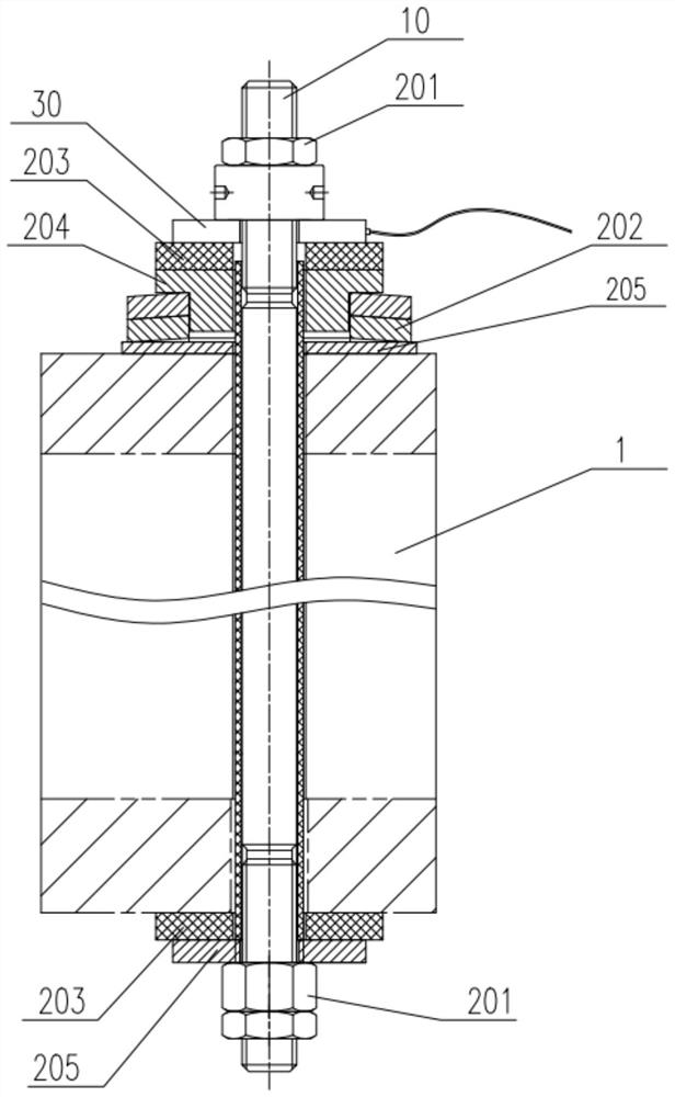
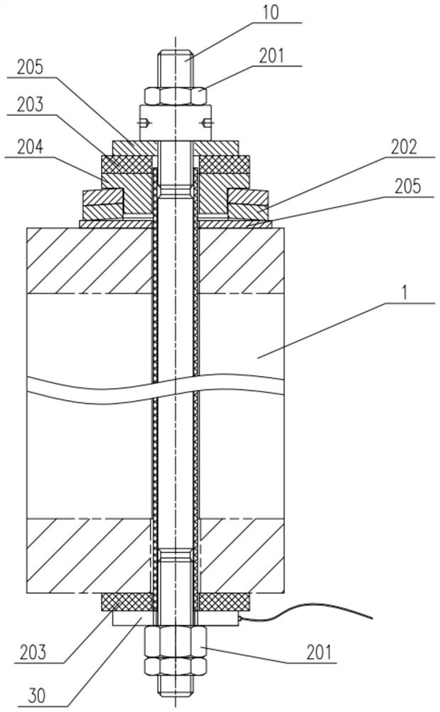
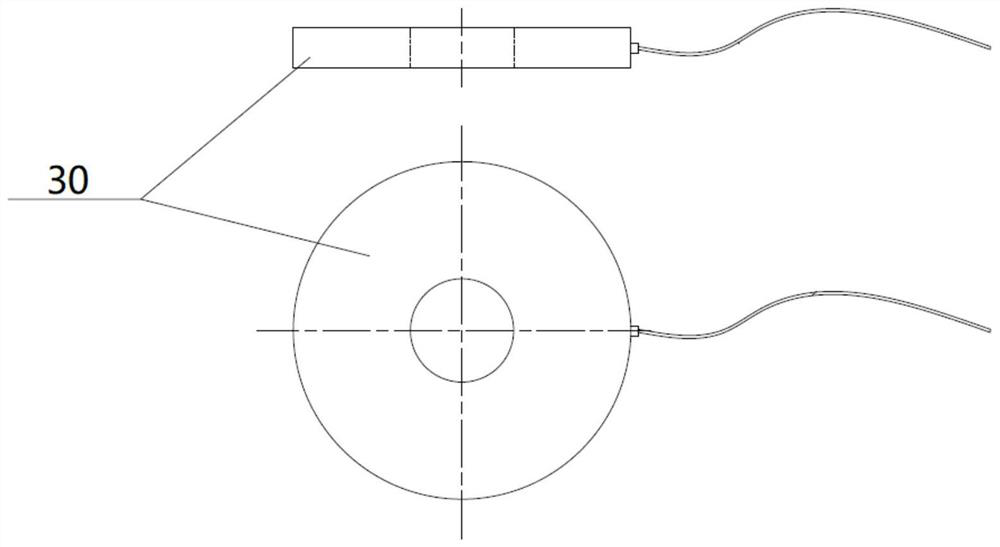
The embodiment of the invention provides a generator set stator structure and a stator measuring point arrangement method, relates to the technical field of hydro-generator operation on-line monitoring, and can detect whether iron core punching sheets in a stator iron core are mutually compressed or not in real time. The fastening assembly is used for keeping the stator core in a compressed state; and the force measuring assembly comprises a pressure sensor, and the pressure sensor is arranged between the stator core and the fastening assembly and is used for measuring a relative pressure value between the stator core and the fastening assembly. According to the generator set stator structure provided by the embodiment of the invention, the compression state of the stator core can be detected in real time, and a corresponding detection assembly does not need to be arranged on the core punching sheet, so that the influence on the stator core is avoided; as the detection device is arranged outside the stator core, the interference of the stator core is less, and the measurement resolution is high; the generator set stator structure provided by the embodiment of the invention adopts an assembly part nesting mode, and is high in integrity.

Description

technical field [0001] The application relates to the technical field of on-line monitoring of hydraulic generator operation, in particular to a stator structure of a generating set and a method for arranging stator measuring points. Background technique [0002] The stator core is formed by stacking multiple core punches. When the core punches are not compressed, the electromagnetic force and mechanical force when the hydro-generator unit is working will cause the core punches to shift in multiple directions. The core punches themselves It is easy to be damaged, and at the same time, the loose core punch may also cause contact friction against the through-core screw, which will damage the insulation layer on the through-core screw and cause a short circuit, resulting in burning accidents of the screw and the contacted core punch; even It is also possible to cut the insulation of the slot part of the stator bar, causing more serious accidents; therefore, it is necessary to o...

Claims


Application Information

Patent Timeline
Patent Type & Authority Applications(China)
IPC IPC(8): H02K1/12H02K1/04H02K11/30H02K15/02H02K15/10G01L1/24
Inventor 高涛铎林刘云平张猛周军长陈旭万慧明罗显莅
Owner DONGFANG ELECTRIC MACHINERY
Learn More