Eureka AIR delivers breakthrough ideas for toughest innovation challenges, trusted by R&D personnel around the world.

Optical module aging test method and system

An aging test and optical module technology, applied in the field of optical communication, can solve the problems of increasing the complexity of production test software, misjudging qualified optical modules as bad, increasing manufacturing costs, etc., so as to improve the efficiency of the aging test, shorten the aging process time, The effect of reducing production costs

Pending Publication Date: 2022-04-08
YANGTZE OPTICAL FIBRE & CABLE CO LTD
View PDF6 Cites 0 Cited by
  • Summary
  • Abstract
  • Description
  • Claims
  • Application Information

AI Technical Summary

Problems solved by technology

This method has the following disadvantages: (1) At least two times of plugging and unplugging of optical fibers are required in the pre-aging and post-aging tests, and each plugging and unplugging of optical fibers will bring test errors; (2) This process requires multiple adjustments of bias current, Increases the complexity of the production test software, which is easy to cause confusion; (3) For the same optical module, the machines tested before and after burn-in are usually not the same test system, and there are fixed test deviations between systems, including optical fiber Own loss and deviation caused by optical power meter
The above deficiencies may cause a certain proportion of qualified optical modules to be misjudged as bad, which increases the manufacturing cost

Method used


Image

  • Optical module aging test method and system
  • Optical module aging test method and system

Examples


Embodiment Construction

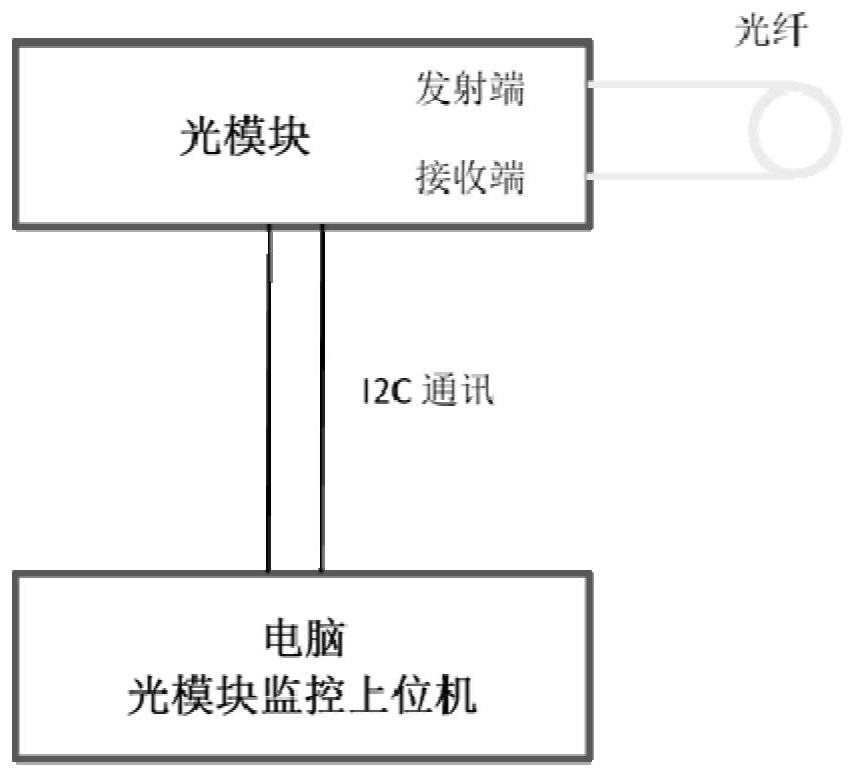
[0028] In order to make the object, technical solution and advantages of the present invention clearer, the present invention will be further described in detail below in conjunction with the accompanying drawings and embodiments. It should be understood that the specific embodiments described here are only used to explain the present invention, not to limit the present invention. In addition, the technical features involved in the various embodiments of the present invention described below can be combined with each other as long as they do not constitute a conflict with each other.

[0029] An optical module aging test method in an embodiment of the present invention is applied to an optical module with a monitoring function, that is, the optical module includes an optical transmitting port, an optical receiving port, and a monitoring module, and the monitoring module is used to generate a monitoring module based on a signal received by the optical receiving port. The value,...


PUM


Abstract

The invention discloses an optical module aging test method and system, the optical module comprises an optical transmitting port, an optical receiving port and a monitoring module, and the monitoring module is used for generating a monitoring value according to a signal received by the optical receiving port. The method comprises the following steps: connecting the light transmitting port and the light receiving port through an optical fiber; reading monitoring values of the monitoring module before and after aging, and outputting an aging test result according to changes of the monitoring values before and after aging; in addition, the bias current of the optical module can be adjusted according to a mapping table of the bias current and the temperature. According to the invention, the misjudgment rate of poor aging is reduced, the aging test efficiency is improved, and the aging test cost is reduced.

Description

technical field [0001] The invention belongs to the technical field of optical communication, and more particularly relates to an optical module aging test method and system. Background technique [0002] The optical module is mainly used for the transmission and reception of optical signals, and is the core device in the optical fiber communication system. The optical module aging process is an important process in the production process. Its main purpose is to screen out lasers with weak reliability through the aging process to avoid early failure of the optical modules shipped to the client, so as to ensure the smooth operation of the optical communication network. [0003] The current aging process needs to go through the main steps of pre-aging test, aging in the aging environment test chamber, post-aging test and judging whether it is qualified or not. Such as figure 1 As shown, it specifically includes: (1) firstly carry out the pre-aging test, insert the optical mo...

Claims


Application Information

Patent Timeline
Patent Type & Authority Applications(China)
IPC IPC(8): H04B10/079G01K13/00
Inventor 薄生伟
Owner YANGTZE OPTICAL FIBRE & CABLE CO LTD
Why Eureka
Eureka Blog
Learn More