Supercharge Your Innovation With Domain-Expert AI Agents!

Dispersion shaft circulating cooling system

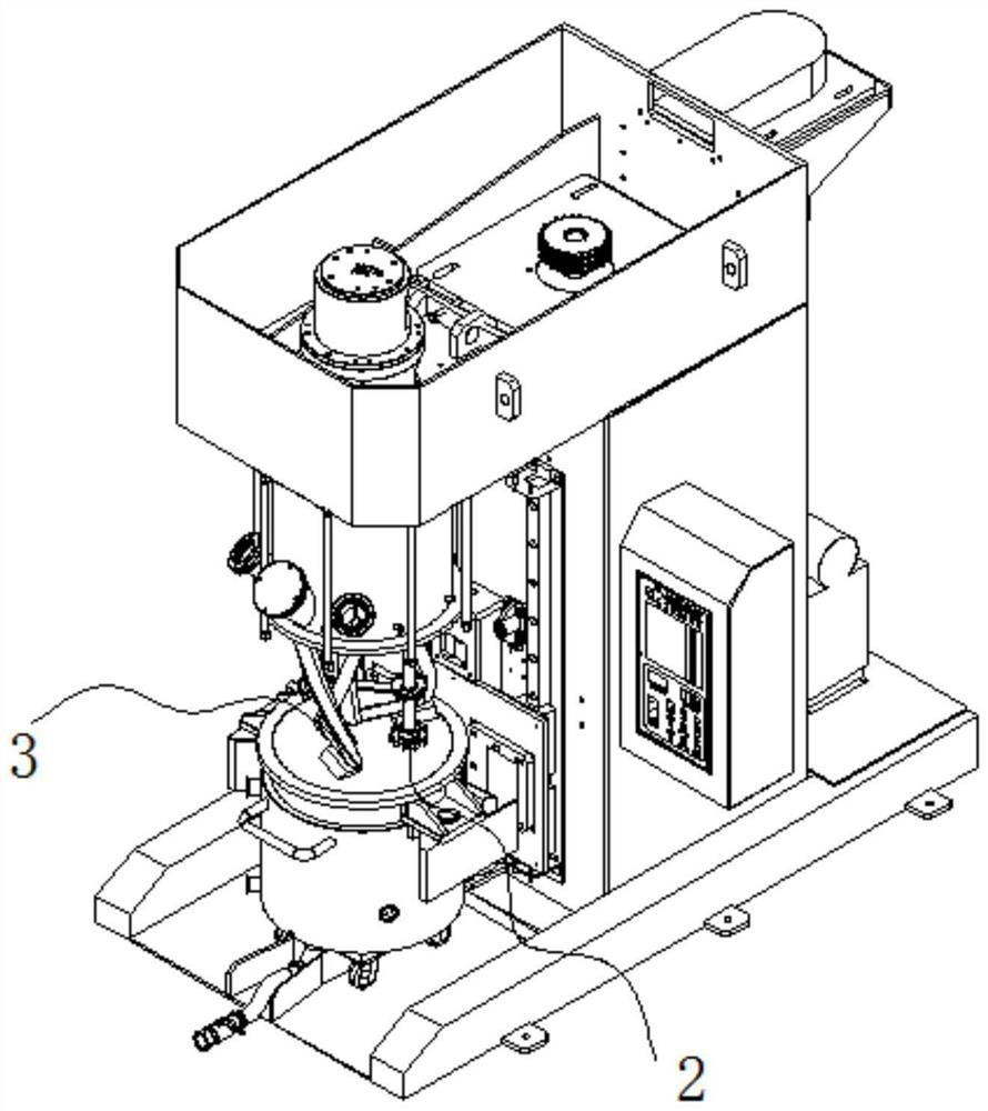
A technology of circulating cooling system and dispersing shaft, which is applied in the directions of dissolving, mixer, chemical instruments and methods, can solve the problems such as the temperature rise of stirring slurry and affect the stirring quality, and achieve the effect of ensuring the stirring quality and improving the stirring efficiency.

Pending Publication Date: 2022-04-12
湖南锦熹智能科技有限公司
View PDF0 Cites 0 Cited by
  • Summary
  • Abstract
  • Description
  • Claims
  • Application Information

AI Technical Summary

Problems solved by technology

Because in the stirring process, especially in the high-speed stirring process, the stirring paddle and the dispersing shaft are mainly used for stirring and dispersing, and the stirring paddle and the dispersing shaft are surrounded by the slurry and are located inside the slurry, and will interact with the slurry during the stirring process. Generate friction and generate heat. The heat is condensed around the stirring paddle and the dispersing shaft, and is not easy to dissipate from the outside, which will lead to an increase in the temperature of the stirring paddle, dispersing shaft and the stirring slurry, affecting the stirring quality.
Therefore, there are still many unreasonable places in the traditional mixer cooling technology, which needs to be improved and perfected.

Method used


Image

  • Dispersion shaft circulating cooling system
  • Dispersion shaft circulating cooling system
  • Dispersion shaft circulating cooling system

Examples


Embodiment Construction

[0046] The technical solutions in the embodiments of the present invention will be clearly and completely described below in conjunction with the accompanying drawings. Apparently, the described embodiments are only part of the embodiments of the present invention, not all of them. Based on the embodiments of the present invention, all other embodiments obtained by persons of ordinary skill in the art without creative efforts fall within the protection scope of the present invention.

[0047] It should be noted that if the embodiment of the present invention involves directional indications (such as up, down, left, right, front, back, top, bottom, inside, outside, vertical, horizontal, vertical, counterclockwise, clockwise, circumferential direction, radial direction, axial direction...), the directional indication is only used to explain the relative positional relationship, movement conditions, etc. When a change occurs, the directional indication changes accordingly.

[00...


PUM


Abstract

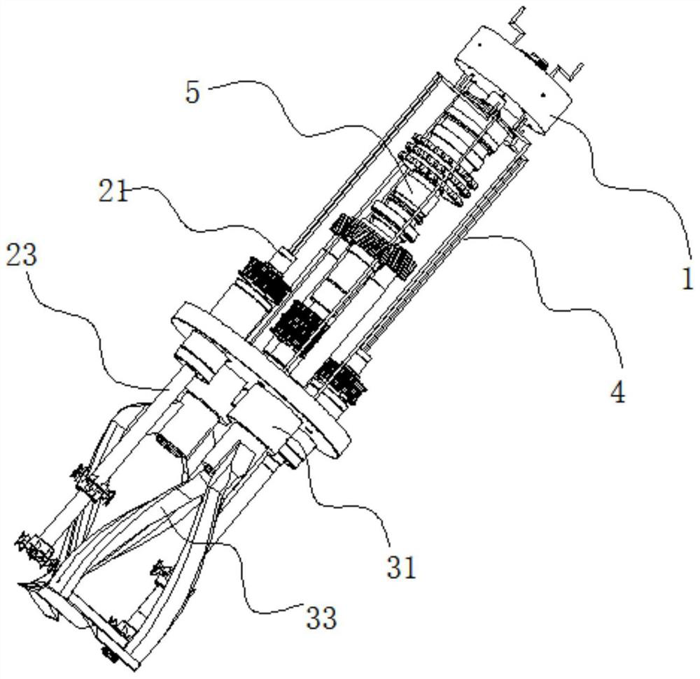
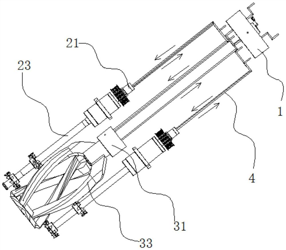
The invention discloses a dispersion shaft circulating cooling system which comprises a dispersion shaft and a dispersion shaft connector, the dispersion shaft connector comprises a dispersion shaft outer connector and a dispersion shaft inner connector, the dispersion shaft inner connector is rotatably assembled on the inner side of the dispersion shaft outer connector, and the dispersion shaft outer connector is provided with a dispersion shaft outer connector water inlet channel and a dispersion shaft outer connector water outlet channel. The dispersion shaft inner joint is provided with a dispersion shaft inner joint water inlet channel and a dispersion shaft inner joint water outlet channel; the dispersing shaft outer connector water inlet channel is arranged in the center of the dispersing shaft outer connector, the dispersing shaft inner connector water inlet channel is arranged in the center of the dispersing shaft inner connector, the dispersing shaft outer connector water inlet channel and the dispersing shaft inner connector water inlet channel are communicated in a butt joint mode, and the dispersing shaft inner connector and the dispersing shaft outer connector are matched inside and outside. And the water outlet channel of the dispersion shaft inner joint is communicated with the water outlet channel of the dispersion shaft outer joint through the dispersion shaft outflow cavity. And circulating cooling is carried out on the dispersion shaft.

Description

technical field [0001] The invention relates to the cooling technology of a mixer, in particular to a circulating cooling system for a dispersion shaft. Background technique [0002] Mixers are used in many fields, such as lithium batteries, chemical industry, and food industry. The mixer is prone to generate heat during the mixing process, and if the heat cannot be dissipated in time, it will cause the temperature of the mixing slurry to rise, affect the quality, and even It also causes the slurry to be scrapped, affecting the stirring efficiency, and only controlling the speed (reducing speed and efficiency) to control the temperature. The current agitator can only be cooled by agitating the barrel body of the agitator and circulating cooling water. This traditional cooling method of cooling through the barrel of the mixing tank belongs to the external cooling of the periphery of the slurry during the mixing process. Although it can achieve a certain cooling effect, it is...

Claims


Application Information

Patent Timeline
IPC IPC(8): B01F27/90B01F27/93B01F27/21B01F35/95B01F27/2322
Inventor 何志凌何志虹张朝林
Owner 湖南锦熹智能科技有限公司
Features
  • R&D
  • Intellectual Property
  • Life Sciences
  • Materials
  • Tech Scout
  • Unparalleled Data Quality
  • Higher Quality Content
  • 60% Fewer Hallucinations
Learn More