Hydraulic pipe bending machine for leisure crafts
A technology of pipe bending machines and handicrafts, applied in the direction of manufacturing tools, metal processing equipment, feeding devices, etc., can solve the problems of labor and low device efficiency, and achieve the effects of improving work efficiency, convenient bending, and convenient adjustment
- Summary
- Abstract
- Description
- Claims
- Application Information
AI Technical Summary
Problems solved by technology
Method used
Image
Examples
Embodiment 1
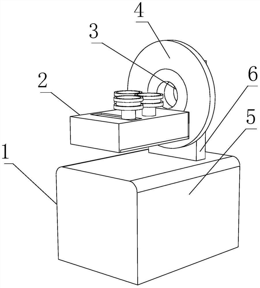
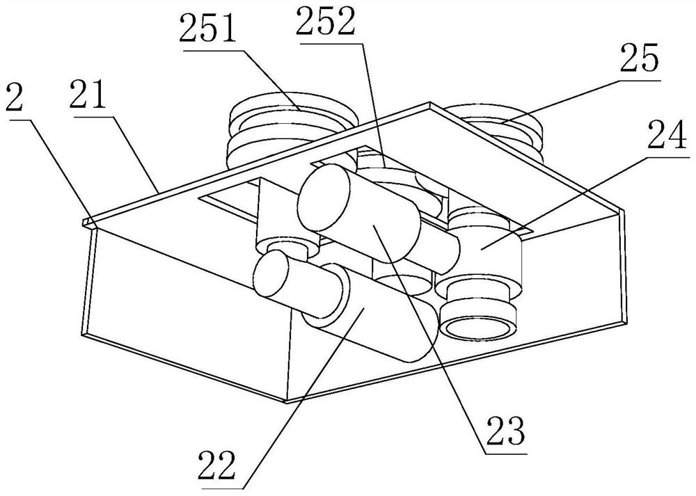
[0033] like Figure 1-6 As shown, the present invention provides a hydraulic pipe bender for leisure handicrafts, the pipe bending device main body 1, the pipe bending device main body 1 includes a base 5, the top of the base 5 is fixedly connected with a fixing frame 6, and the top of the base 5 is provided with a The bending device 2, one side of the bending device 2 is fixedly connected with a rotating device 4, the inner wall of the rotating device 4 is movably connected with a fixing device 3, the bending device 2 includes a casing 21, and the inner wall of the casing 21 is fixedly connected with a first hydraulic pressure Rod 22, one side of the first hydraulic rod 22 is provided with a second hydraulic rod 23, one end of the second hydraulic rod 23 is provided with a lifting device 24 and a first pressure roller 25, and the fixing device 3 includes a movable ring 31, a movable ring 31 The inner wall of the fixed ring 35 is fixedly connected with a fixed ring 35, the ins...
Embodiment 2
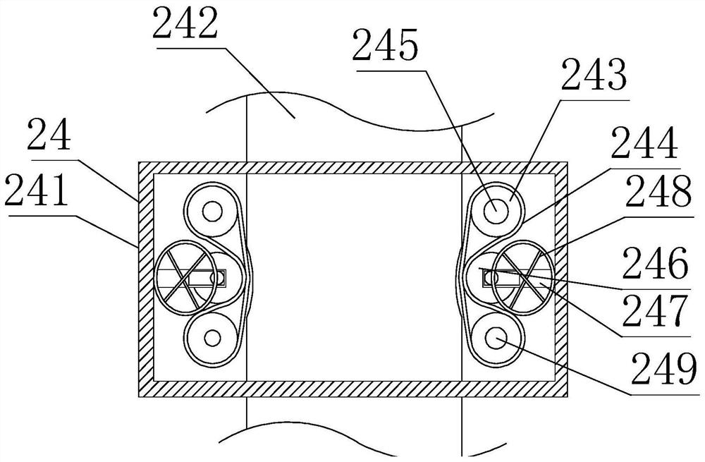
[0035] like Figure 1-6As shown, on the basis of Embodiment 1, the present invention provides a technical solution: preferably, the lifting device 24 includes a protective shell 241, the inner wall of the protective shell 241 is movably connected with a slide bar 242, and the outer wall of the slide bar 242 is provided with a groove, the top of the slide bar 242 is movably connected with the inner wall of the first pressure roller 25, the inner wall of the protective shell 241 is movably connected with the first motor 245, and the output shaft of the first motor 245 is fixedly connected with the first runner 243, the first The outer wall of runner 243 is movably connected with crawler belt 244, and the outer wall of crawler belt 244 is movably connected with second runner 246, and the both sides of second runner 246 is movably connected with fixed rod 247, and one end of fixed rod 247 and the inner wall of protective shell 241 Fixed connection, one side of the second runner 24...
Embodiment 3
[0037] like Figure 1-6 As shown, on the basis of Embodiment 1, the present invention provides a technical solution: the inner wall of the preferred movable ring 31 is fixedly connected with an elastic rod 32, the outer wall of the elastic rod 32 is fixedly connected with a moving rod 33, and the outer wall of the moving rod 33 A sliding column 34 is movably connected, the bottom of the sliding column 34 is fixedly connected with the outer wall of the fixed ring 35, the inner side of one end of the moving rod 33 is movably connected with both sides of the movable wheel 36, and one side of the moving rod 33 is fixedly connected with a second motor 38 , the output shaft of the second motor 38 is fixedly connected with one end of the movable wheel 36, the outer wall of the movable wheel 36 is fixedly connected with a protective pad 37, the moving rod 33 is squeezed by the elastic rod 32, and the sliding column 34 is used to move. Wheel 36 squeezes and fixes the steel pipe, rotate...
PUM
 Abstract
Description
Claims
Application Information
 - R&D
- Intellectual Property
- Life Sciences
- Materials
- Tech Scout
- Unparalleled Data Quality
- Higher Quality Content
- 60% Fewer Hallucinations
Browse by: Latest US Patents, China's latest patents, Technical Efficacy Thesaurus, Application Domain, Technology Topic, Popular Technical Reports.
© 2025 PatSnap. All rights reserved.Legal|Privacy policy|Modern Slavery Act Transparency Statement|Sitemap|About US| Contact US: help@patsnap.com


