Grinding equipment for inner wall of carbon steel material pipeline

A carbon steel pipe and grinding technology, which is applied in the direction of grinding/polishing equipment, machine tools designed for grinding the rotating surface of workpieces, grinding racks, etc. major issues

Pending Publication Date: 2022-04-12
邱旺旺
View PDF9 Cites 0 Cited by
  • Summary
  • Abstract
  • Description
  • Claims
  • Application Information

AI Technical Summary

Problems solved by technology

[0004] In order to overcome the common grinding equipment on the market, after the carbon steel pipe is ground, the carbon steel pipe needs to be manually unloaded, which requires a lot of labor, and the carbon steel pipe is easy to hit the foot, which is dangerous. The technical problem of the present invention is: Provide a safe, non-manual unloading carbon steel pipe inner wall grinding equipment

Method used


Image

  • Grinding equipment for inner wall of carbon steel material pipeline
  • Grinding equipment for inner wall of carbon steel material pipeline
  • Grinding equipment for inner wall of carbon steel material pipeline

Examples


Embodiment 1

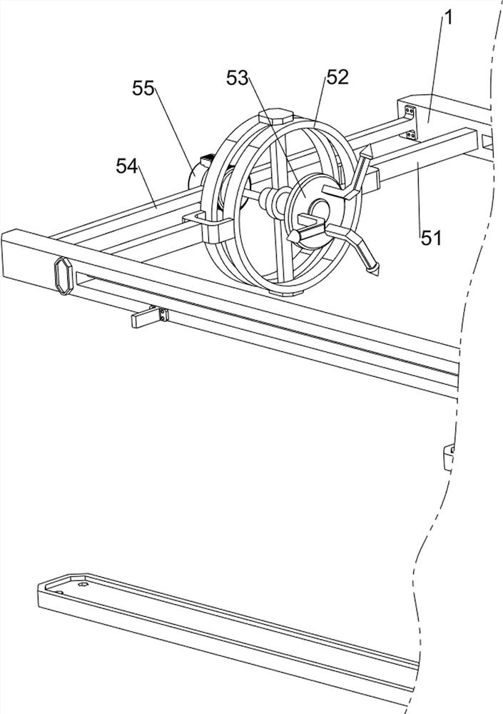
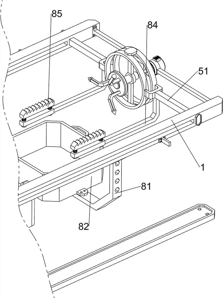
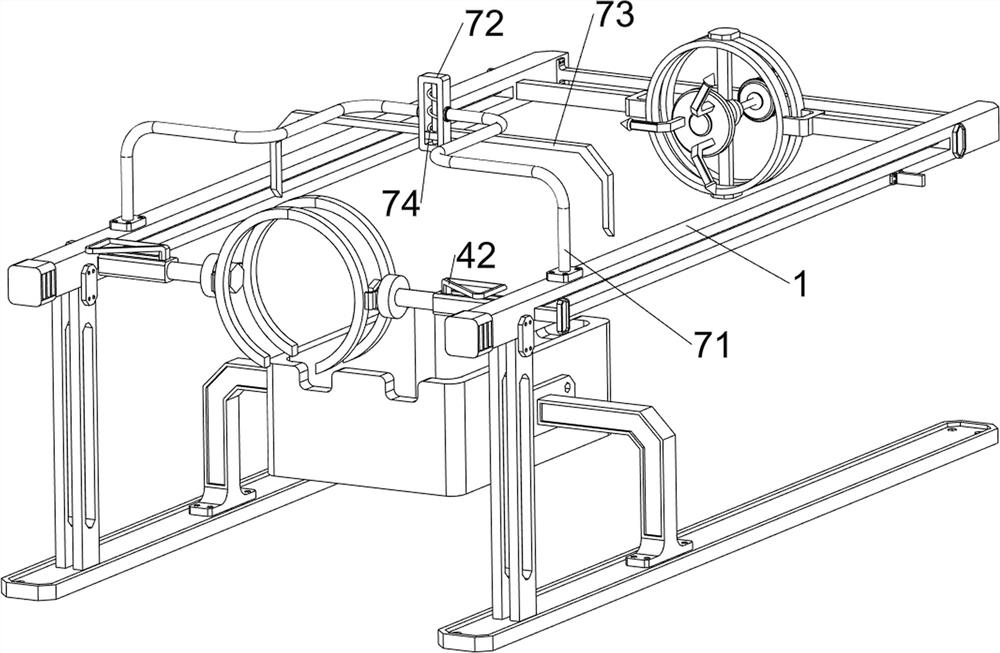
[0038] A kind of carbon steel material pipe inner wall grinding equipment, such as Figure 1-5 As shown, it includes a frame 1, a first fixed block 2, a charging box 3, a clamping mechanism 4 and an abrasive mechanism 5. There are two frames 1 in total, and the frames 1 are arranged symmetrically front and back. The first fixed block 2, a charging box 3 is arranged between the two first fixed blocks 2, a clamping mechanism 4 is slidably arranged between the upper left sides of the two frames 1, and a clamping mechanism 4 is arranged between the upper right sides of the two frames 1. There is an abrasive mechanism 5, which is located on the right side of the clamping mechanism 4.

[0039] When people need to grind the inner wall of the carbon steel pipe, people can first start the clamping mechanism 4 to work, so that the clamping mechanism 4 clamps the carbon steel pipe, and then the clamping mechanism 4 can be pushed to the right, so that the clamping mechanism 4 Drive the c...

Embodiment 2

[0045] On the basis of Example 1, such as figure 1 , Figure 6 , Figure 7 , Figure 8 , Figure 9 , Figure 10 , Figure 11 , Figure 12 , Figure 13 , Figure 14 and Figure 15 As shown, a transmission mechanism 6 is also included, and the transmission mechanism 6 includes a worm screw 61, a third fixed block 62, a connecting rod 63, a worm wheel 64, a fourth fixed block 65, a bevel gear 66, a roller 67, a second sliding block 68, The first fixed rod 69, the third connecting block 610, the third spring 611, the rope 612 and the fourth spring 613, the right side of the output shaft of the motor 55 is provided with a worm 61, and the right side of the rear frame 1 top is provided with a third fixed block 62 , the front side of the third fixed block 62 is rotatably provided with a connecting rod 63, the bottom of the connecting rod 63 is provided with a worm wheel 64, the worm wheel 64 is engaged with the worm 61, and the right side of the front frame 1 is provided wit...


PUM


Abstract

The invention relates to grinding equipment, in particular to carbon steel material pipeline inner wall grinding equipment. The invention provides the carbon steel material pipeline inner wall grinding equipment which is safe and does not need manual unloading. Carbon steel material pipeline inner wall grinding equipment comprises first fixing blocks and two frames, the frames are symmetrically arranged, and the first fixing blocks are arranged on one sides of the lower portions of the two frames; the charging box used for collecting the carbon steel pipes is arranged between the two first fixing blocks; and the clamping mechanism used for clamping the carbon steel pipe is arranged between one sides of the upper parts of the two frames in a sliding manner. The carbon steel pipe can be clamped under the action of the rotating block, the first sliding block can be pushed rightwards after clamping, the rotating block is driven to move rightwards, and then the carbon steel pipe is driven to move rightwards for grinding work, so that manual direct contact with the carbon steel pipe is not needed, and the carbon steel pipe can be prevented from rotating and displacing in the grinding work.

Description

technical field [0001] The invention relates to a grinding device, in particular to a grinding device for the inner wall of a carbon steel material pipeline. Background technique [0002] Carbon steel pipes are made of steel ingots or solid round steel through perforation, and then hot rolled, cold rolled or cold drawn. They are often used in refrigeration, HVAC, water pipes, steam pipes, oil pipes and other fields. When steel pipes are being processed, one side of the inner wall of the carbon steel pipe needs to be ground, and the inner wall can be ground evenly before it can be hinged with other carbon steel pipes, which can be used for oil pipes. The common grinding equipment on the market, after the carbon steel pipe is ground , the carbon steel pipe needs to be unloaded manually, the labor force is large, the work efficiency is low, and the carbon steel pipe hits the worker's foot during manual unloading, which is very dangerous. [0003] Therefore, it is necessary to ...

Claims


Application Information

Patent Timeline
Patent Type & Authority Applications(China)
IPC IPC(8): B24B5/40B24B5/35B24B41/06B24B41/02B24B47/12B24B55/12
CPCY02P70/10
Inventor 邱旺旺
Owner 邱旺旺
Why Eureka
Try Eureka