Pre-plasticized backpressure change-over valve block of injection molding machine

An injection molding machine and back pressure technology, which is applied in the field of injection molding machine pre-molded back pressure switching valve block, can solve the problems of reducing spring force, reducing the assembly space of switching valve block, reducing the volume of valve block, and high pressure regulation deviation. Spring force, avoiding the effect of non-integrated installation and avoiding biased pressure regulation

Pending Publication Date: 2022-04-12
NINGBO HAIDA PLASTIC MACHINERY
View PDF4 Cites 0 Cited by
  • Summary
  • Abstract
  • Description
  • Claims
  • Application Information

AI Technical Summary

Problems solved by technology

[0005] In order to solve the technical problems existing in the background technology, the present invention proposes a premolded back pressure switching valve block for injection molding machines. The present invention utilizes the principle of installing a Burst pulsation damper inside the switching valve block to prevent the liquid from flowing too violently As a result, the "water hammer effect" will damage the conversion valve block and other valve components in the conversion valve block. The pilot relief valve is easy to insert, and the assembly space and valve block volume of the conversion valve block are reduced, which is beneficial Overhaul and replacement of the relief valve, and avoid the disadvantage that the pilot-operated relief valve cannot be installed in an integrated manner, and reduce the spring force inside the cartridge-type relief valve to avoid pressure adjustment deviation caused by excessive spring stiffness high

Method used


Image

  • Pre-plasticized backpressure change-over valve block of injection molding machine
  • Pre-plasticized backpressure change-over valve block of injection molding machine
  • Pre-plasticized backpressure change-over valve block of injection molding machine

Examples


Embodiment 1

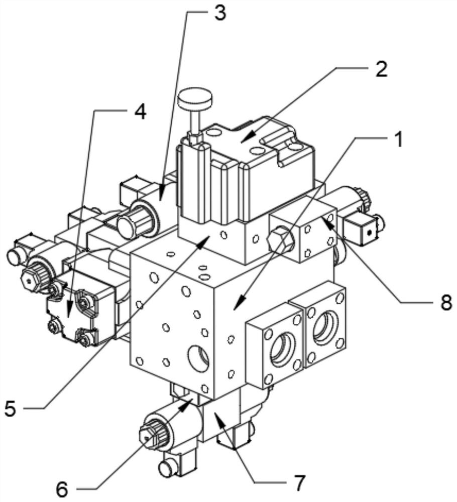
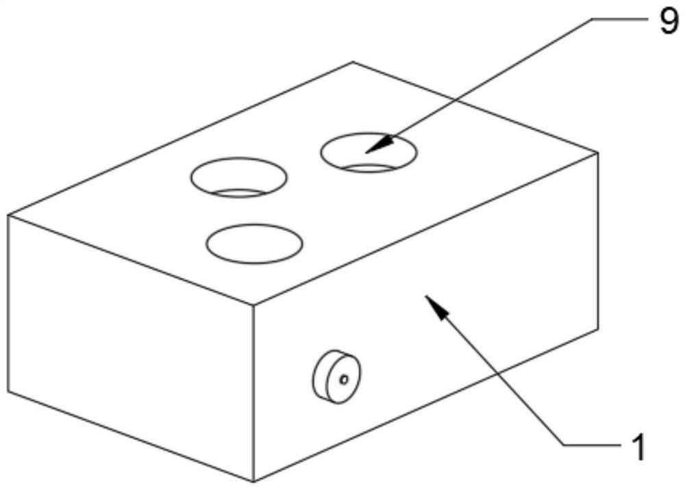
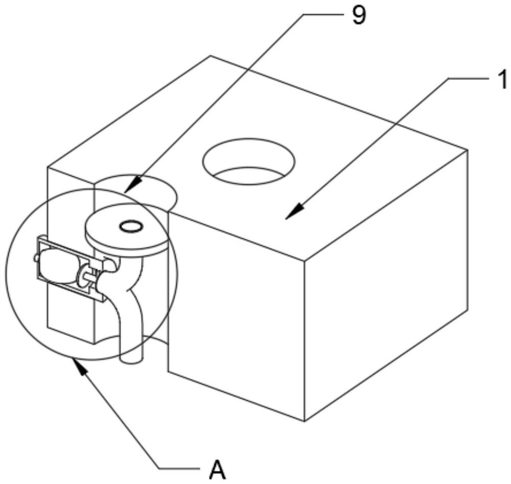
[0029] Embodiment one: refer to Figure 1-7 , a premolded back pressure switching valve block for an injection molding machine, comprising an injection valve block 1, a superimposed valve block 5 is provided on the top surface of the injection valve block 1, and a plug-in pilot relief valve 2 is provided on the top surface of the superimposed valve block 5 , the plug-in pilot relief valve 2 is equipped with a plug-in overflow structure B through opening a threaded hole pipe, and a plurality of valve holes 9 are opened on the surface of the injection valve block 1, and the inside of the valve holes 9 is equipped with a damping structure A , the plug-in overflow structure B includes a threaded housing 18 and a sealing sleeve 22, the bottom opening of the threaded housing 18 is fixedly connected with the top opening of the sealing sleeve 22, and the sealing sleeve 22 is inserted into the through hole on the surface of the stacked valve block 5, and the After screwing the adjustin...

Embodiment 2

[0030] Embodiment two: refer to Figure 1-7, on the basis of Embodiment 1, a pre-molded back pressure conversion valve block for an injection molding machine, one end of the adjusting bolt 20 located at the top of the threaded casing 18 is provided with an adjusting nut 19, and both sides of the limit piece 24 are provided with a circle The inside of the round hole is provided with a cylindrical spring, the top of the threaded housing 18 is provided with a through hole for the adjustment bolt 20 to pass through, and the bottom of the sealing sleeve 22 is provided with a through hole for the movable column 21 to pass through, and the sealing sleeve 22 There are overflow ports on both sides of the cover, and the overflowing liquid will enter through the bottom through hole of the sealing sleeve 22, and flow away at the overflow ports on both sides of the sealing sleeve 22, so as to realize the effect of the overflow valve. The threaded housing 18 The outer ring of the plug-in pi...

Embodiment 3

[0031] Embodiment three: refer to Figure 1-7 , on the basis of Embodiment 2, a premolded back pressure conversion valve block for an injection molding machine, the damping structure A includes a damper housing 17, the side walls of the valve holes 9 are provided with through holes, and the inner walls of the through holes and the damper The outer ring of the casing 17 is clamped, and the end of the damper casing 17 located inside the valve hole 9 is covered with a liquid inlet pipe 12 and a liquid outlet pipe 13, and the end of the liquid inlet pipe 12 far away from the damper casing 17 is covered with a liquid blocking plate 10. The outer ring of the liquid blocking plate 10 is welded to the inner wall of the valve hole 9, and the damper housing 17 is provided with an air bag inflation valve 16 at one end outside the injection valve block 1, and the other end of the air bag inflation valve 16 is provided with a valve located at the damper housing. 17 inside the air bag 15, a...


PUM


Abstract

The invention discloses a pre-plasticized backpressure conversion valve block of an injection molding machine, relates to the field of valve block equipment, and provides the following scheme aiming at the problems that manual control of the injection molding machine is not convenient for electro-hydraulic control and the like: the pre-plasticized backpressure conversion valve block comprises an injection valve block, and a sandwich valve block is arranged on the top surface of the injection valve block; a plug-in type pilot overflow valve is arranged on the surface of the top of the sandwich valve block. By means of the principle that the bursad pulsation damper is installed in the change-over valve block, damage to the change-over valve block and other valve components in the change-over valve block due to the water hammer effect caused by too violent flowing of liquid is prevented, the pilot overflow valve is subjected to insertion treatment conveniently, the assembly space of the change-over valve block and the size of the valve block are reduced, and the cost is reduced. The overflow valve is convenient to maintain and replace, the defect that a pilot-operated type overflow valve cannot be installed in an integrated mode is overcome, the spring force in the plug-in type overflow valve is reduced, and high pressure adjusting deviation caused by too high spring rigidity is avoided.

Description

technical field [0001] The invention relates to the field of valve block equipment, in particular to a premolded back pressure switching valve block for an injection molding machine. Background technique [0002] In the existing injection molding machines, the manual control method of pre-molding back pressure is still widely used, but with the advancement of electro-hydraulic proportional technology and the increasing requirements for the quality of plastic products, the electro-hydraulic proportional control method of pre-molding back pressure , is being used more and more, and the back pressure of the injection molding machine refers to the pressure of the hydraulic cylinder behind the injection screw, that is, the pressure of the injection cylinder during pre-molding, high back pressure, slow pre-molding, low back pressure, fast pre-molding, and back pressure refers to It is the pressure at the back end, and is usually used to describe the pressure opposite to the direct...

Claims


Application Information

Patent Timeline
Patent Type & Authority Applications(China)
IPC IPC(8): B29C45/82B29C45/17
Inventor 沈良聪
Owner NINGBO HAIDA PLASTIC MACHINERY
Why Eureka
Try Eureka