Calendaring forming device for preparing anti-sticking gas mold material
A technology of air mold material and calendering, applied in cleaning methods and utensils, cleaning methods using tools, chemical instruments and methods, etc., can solve problems such as lack of adhesive cleaning measures
Pending Publication Date: 2022-04-12
FUJIAN SIJIA ENVIRONMENTAL PROTECTION MATERIAL TECH
0 Cites 1 Cited by
AI-Extracted Technical Summary
Problems solved by technology
[0006] The invention provides a calendering device for preparing anti-adhesive gas mold materials, which ...
Method used
By setting the cleaning structure 3 on the outside of the lower pressure roller 22, it is mainly used to clean up the adhesive on the lower pressure roller 22, wherein the telescopic scraper assembly 32 and cooling Components 35 are respectively used to quickly cool the adhesive to make it air-dry, and then remove it by the scraper component 32, thereby realizing rapid removal of the adhesion, avoiding long-term adsorption on the outside of the lower pressure roller 22, and affecting the lower pressure roller 22 is used normally, so that the pressing structure 2 has an automatic cleaning function, which is safer and more worry-free during use.
The cleaning structure 3 is mainly used to clean up the adhesive agent outside the lower pressure roller 22 by being arranged on the outside of the lower pressure roller 22, and the tops of the front and rear sides of the casing 31 are respectively connected with the outside of the rotating shaft of the lower pressure roller 22 front and rear sides. Socketing, one side of which is provided with a box door, by opening the box door, the adhesive accumulated inside it is cleaned, and at the same time it is convenient to repair and replace the scraper assembly 32, and it will not affect the rotation of the shaft. The front and rear sides are respectively It is fixedly installed with the front and rear sides of the inner wall of the main body frame 1, so that it can be stably installed at the bottom position of the lower pressure roller 22;
The groove provided on the bottom plate 321 is adapted to the protrusion on the ins...
Abstract
The invention provides a calendaring forming device for preparing an anti-sticking gas mold material. The calendaring forming device for preparing the anti-sticking gas mold material comprises a main body frame pressing structure, the pressing structure is arranged between the two sides of the inner wall of a main body frame, and the pressing structure comprises an upper pressing roller and a lower pressing roller. According to the calendaring forming device for preparing the anti-sticking gas mold material, the cleaning structure is arranged outside the lower pressing roller and is mainly used for cleaning an adhesive outside the lower pressing roller, and the telescopic scraping plate assembly and the cooling assembly are arranged below the lower pressing roller, so that the adhesive outside the lower pressing roller can be cleaned; according to the press-fit structure, the two air-drying devices are used for rapidly cooling and air-drying an adhesive and then removing the adhesive through the scraper assembly, so that the adhesive is rapidly removed, the situation that the adhesive is adsorbed outside the lower press roller for a long time and normal use of the lower press roller is affected is avoided, the press-fit structure has an automatic cleaning function, and the press-fit structure is safer and more worry-saving in use.
Application Domain
Cleaning using tools
Technology Topic
EngineeringAdhesive +4
Image
Examples
- Experimental program(2)
Example
[0040] first embodiment
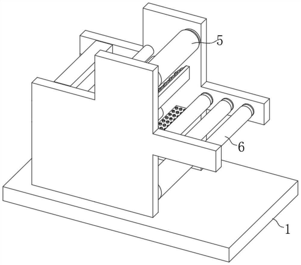
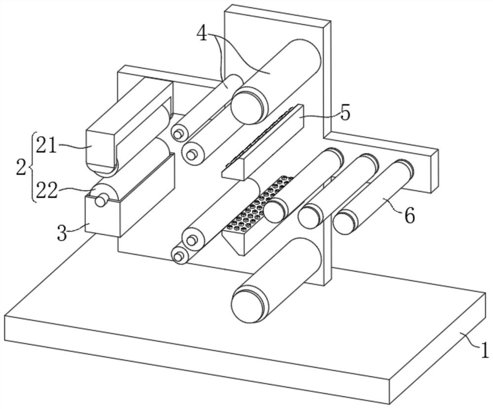
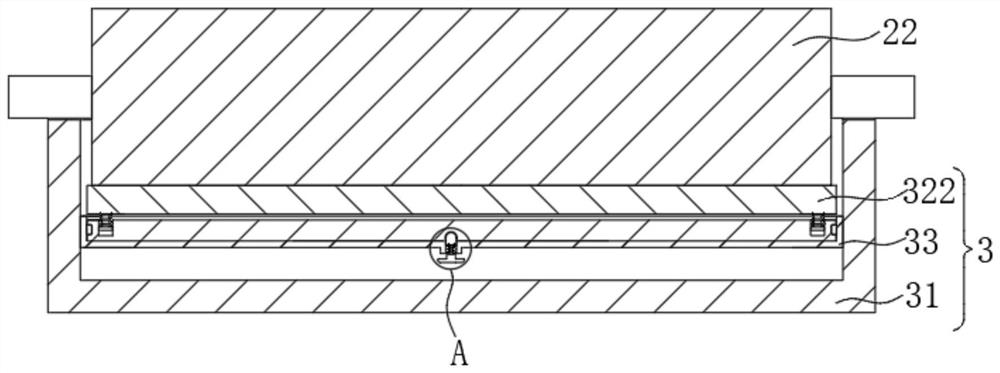
[0041] Please refer to figure 1 , figure 2 , image 3 , Figure 4 , Figure 5 ,in, figure 1 It is a schematic structural diagram of the first embodiment of the calendering device for the preparation of the anti-stick gas mold material provided by the present invention; figure 2 for figure 1 The schematic diagram of the inner side of the main frame shown; image 3 for figure 1 The schematic diagram of the internal structure of the box shown; Figure 4 for image 3 The enlarged schematic diagram of Part A shown; Figure 5 for image 3 Sectional view of plane A-A shown. Anti-adhesive calendering equipment for the preparation of air-mold materials, including:
[0042] main frame 1
[0043] Press-fit structure 2, which is arranged between two sides of the inner wall of the main frame 1, and the press-fit structure 2 includes an upper pressure roller 21 and a lower pressure roller 22;
[0044] Cleaning structure 3, the cleaning structure 3 is arranged at the bottom of the lower pressure roller 22, the cleaning structure 3 includes a box body 31, the box body 31 is installed on the bottom of the lower pressure roller 22, the box body The inside of 31 is provided with a cooling component 35 for blowing the lower wind force on the outside of the lower pressure roller 22, a scraper component 32 for scraping the adhesive on the outside of the lower pressure roller 22, and a The scraper assembly 32 provides a supporting mounting seat 33 , and a clamping assembly 34 for fixing the scraper assembly 32 is provided in the middle of the mounting seat 33 ;
[0045] The scraper assembly 32 includes a bottom plate 321 and a contact scraper 322, the bottom plate 321 is mounted on the inner side of the mounting seat 33, the contact scraper 322 is located directly above the bottom plate 321, and the contact scraper The top of the 322 is attached to the bottom of the outside of the lower pressing roller 22 , and connecting rods 323 are fixedly installed on both sides of the bottom of the contact scraper 322 , and the bottom end of the connecting rod 323 slides with the inside of the bottom plate 321 For connection, a support spring 324 is sleeved on the outside of the connecting rod 323 .
[0046] The pressing structure 2 is arranged on the left side of the inner wall of the main frame 1, and is used for the final pressing of the material;
[0047]The cleaning structure 3 is arranged on the outside of the lower pressing roller 22, and is mainly used for cleaning the adhesive outside the lower pressing roller 22. A box door is provided on one side of the box. By opening the box door, the accumulated adhesive can be cleaned, and the scraper assembly 32 can be easily repaired and replaced without affecting the rotation of the rotating shaft. The front and rear sides of the box are respectively connected to the main frame. 1 The front and rear sides of the inner wall are fixedly installed, so that it can be stably installed at the bottom of the lower pressure roller 22;
[0048] The cooling component 35 mainly cools the adhesive adsorbed on the outside of the lower pressure roller 22 quickly, so that it can be quickly cooled to dry and harden, and then it is convenient to contact the scraper 322 to remove it from the outside of the lower pressure roller 22, The scraper assembly 32 is arranged at the bottom of the lower pressing roller 22 to remove the adhesive adhered to the outside thereof. The mounting seat 33 is used in conjunction with the scraper assembly 32 as a mounting and supporting structure for the scraper assembly 32. The connecting assembly 34 is arranged inside the mounting seat 33, and is mainly used to effectively fix the bottom of the scraper assembly 32, so that the scraper assembly 32 can be stably installed inside the box body 31;
[0049] The bottom plate 321 mainly provides support for the contact scraper 322, which is adapted to the mounting seat 33 and can be clamped inside the mounting seat 33, and the top of the contact scraper 322 is in contact with the outer bottom of the lower pressing roller 22. When the 22 rotates, the contact scraper 322 is continuously contacted with its surface, and then the adhesive on the surface is removed. Wear, the connecting rods 323 are located on the front and rear sides of the bottom of the contact scraper 322 respectively. By slidingly connecting with the bottom plate 321, the contact scraper 322 can be effectively connected with the bottom plate 321, and the support spring 324 is located between the bottom of the contact scraper 322 and the bottom plate 321. Between the tops, it mainly provides elastic support for the contact scraper 322. When the contact scraper 322 moves downward, the support spring 324 can be squeezed to contract. The contact scraper 322 is used in conjunction with the support spring 324, so that the contact scraper 322 has elasticity. , when the adhesive has a strong adsorption force and is difficult to be removed, the adhesive block can be pressed down and contacted with the scraper 322 to shrink downward, thereby ensuring that the lower pressing roller 22 can rotate normally and avoiding the influence of The pressing roller 22 rotates.
[0050] The cooling assembly 35 includes a blower 351, the blower 351 is installed inside the casing 31, the output end of the blower 351 is connected with an exhaust duct 352, and the exhaust port on the exhaust duct 352 is aligned Below the outer portion of the lower pressing roller 22 .
[0051] The blower 351 is connected to the power supply inside the box body 31, and its operation is controlled by an external switch. After the power is turned on, it can generate cold air, which can be transported to the exhaust duct 352, and finally flow through the exhaust duct 352 to the outside of the pressing roller 22. The outside of the lower pressure roller 22 is blown to achieve rapid cooling of the external adhesive of the lower pressure roller 22, so that it can be quickly cooled to a dry state, and the cooling assembly 35 is not limited to the form of the blower 351 and the exhaust duct 352, Any one that can achieve cooling of the external adhesive of the lower pressing roller 22 can be used.
[0052] The mounting seat 33 is fixedly mounted on both sides of the inner wall of the box body 31 , and the bottom of the lower pressing roller 22 is located inside the box body 31 .
[0053] The snap-fit assembly 34 includes a pulling member 341 , the pulling member 341 is disposed in the middle of the bottom of the mounting seat 33 , and the top of the pulling member 341 extends from the bottom of the mounting seat 33 to the bottom of the mounting seat 33 . internal.
[0054] The clamping assembly 34 is mainly used for clamping and fixing the bottom of the bottom plate 321, so that it can be stably installed on the mounting seat 33, and the pulling member 341 can slide in the vertical direction inside the mounting seat 33.
[0055] The top of the pulling member 341 is fixedly mounted with a snap-on block 342 , the outside of the snap-on block 342 is slidably connected with the inside of the mounting seat 33 , and the top of the snap-on block 342 is connected to the bottom of the bottom plate 321 . The middle is clamped, and the outer part of the pulling member 341 is sleeved with an elastic member 343 .
[0056] The clamping block 342 is slidably connected to the interior of the mounting seat 33 and can slide vertically inside the mounting seat 33 , and a clamping slot adapted to the clamping block 342 is provided in the middle of the bottom of the bottom plate 321 . The clamping slot is internally clamped, so that the bottom plate 321 can be stably clamped in the interior of the mounting seat 33, and the rapid installation and removal of the scraper assembly 32 is realized, which is convenient for people to replace and maintain the scraper assembly 32, while the elastic member 343 Located at the bottom of the clamping block 342, it mainly provides elastic support for the pulling member 341, so that when the pulling member 341 is no longer pulled, the pulling member 341 is driven to reset, and when the pulling member 341 is pulled, the clamping block 342 can squeeze the elastic force Piece 343 shrinks.
[0057] The left and right sides of the contact scraper 322 are set as two inclined and intersecting slopes, the two connecting rods 323 are located on the front and rear sides of the bottom of the contact scraper 322 respectively, and the support spring 324 is located on the contact scraper 322. between the bottom of the scraper 322 and the top of the bottom plate 321 .
[0058] The front and rear sides of the inner side of the mounting seat 33 are both provided with protrusions, and the front and rear sides of the bottom plate 321 are provided with grooves adapted to the protrusions.
[0059] The grooves provided on the bottom plate 321 are adapted to the protrusions on the inner side of the mounting seat 33. When the bottom plate 321 and the inner side of the mounting seat 33 are installed, the contact scraper 322 can It is stably connected to the mounting seat 33 to increase the connection stability between the two.
[0060] The upper pressing roller 21 is located directly above the lower pressing roller 22, and the gap between the upper pressing roller 21 and the lower pressing roller 22 is used for the passage of the anti-stick air mold material, so that the anti-adhesive air mold material is subjected to Pressed and tightly fitted, two first drive roller groups 4 arranged symmetrically up and down, two heating assemblies 5 and a second drive roller group 6 arranged symmetrically up and down are respectively arranged between two sides of the inner wall of the main frame 1 .
[0061] The two first drive roller sets 4 are respectively used to convey the upper and lower material layers to the lamination structure 2, while the second drive roller set 6 is used to convey the middle layer material, and the heating assembly 5 is mainly used to carry out the material layer. Heat treatment to make it tighter when pressing.
[0062] The working principle of the calendering device for preparing the anti-stick gas mold material provided by the present invention is as follows:
[0063] In normal use, the upper layer material and the lower layer material are respectively installed on the two first drive roller sets 4, and then the middle layer material is installed on the second drive roller set 6, between the first drive roller set 4 and the second drive roller Under the operation of the group 6, the three material layers can move to the position of the pressing structure 2, and when passing through the position of the heating assembly 5, they are rapidly heated and processed, and finally the upper pressing roller 21 in the pressing structure 2 and the lower pressing Under the cooperative extrusion action of the roller 22, the material layers are effectively squeezed together;
[0064] When the material layer is squeezed so that the adhesive inside flows out to the outside of the lower pressing roller 22, by starting the blower 351 at this time, cold air can be generated and transported to the exhaust duct 352, so that the cold air can pass through the exhaust air. The duct 352 is blown to the outside of the lower pressing roller 22, and when the lower pressing roller 22 rotates, it can drive the adhesive adsorbed on the outside to move to the position of the exhaust duct 352, and under the action of cold air, the adhesive can be quickly cooled and air-dried When the dried adhesive moves to the position of the contact blade 322 with the lower pressure roller 22, under the action of the contact blade 322, the adhesive can be removed from the outside of the lower pressure roller 22 and be removed. The adhesive that comes down falls directly on the bottom of the inner wall of the box body 31, and then cleans it up by opening the box door on one side of the box body 31;
[0065] If the adhesive adsorption force is too strong, and the contact scraper 322 cannot remove it, the dried adhesive can press down the contact scraper 322 to move, and the contact scraper 322 drives the connecting rod 323 to the mounting seat. 33 shrinks inside, and the contact scraper 322 moves downward at this time, which will not affect the rotation of the lower pressure roller 22, so that the lower pressure roller 22 continues to rotate downward to ensure that the contact scraper 322 does not hinder the lower pressure roller 22.
[0066] Compared with the related art, the calendering device for the preparation of the anti-stick gas mold material provided by the invention has the following beneficial effects:
[0067] By arranging the cleaning structure 3 outside the lower pressing roller 22, it is mainly used for cleaning the adhesive outside the lower pressing roller 22, wherein by arranging the retractable scraper assembly 32 and the cooling assembly 35 at the lower position of the lower pressing roller 22, They are respectively used to quickly cool the adhesive to make it air dry, and then remove it by the scraper assembly 32, so as to realize the rapid removal of the adhesive, and avoid being adsorbed on the outside of the lower pressure roller 22 for a long time, which will affect the normal use of the lower pressure roller 22. , so that the pressing structure 2 has an automatic cleaning function, which is safer and more worry-free during use.
Example
[0069] Please refer to Image 6 , based on the first embodiment of the present invention, a calendering device for the preparation of anti-adhesive air mold materials, the second embodiment of the present invention provides another calendering device for the preparation of anti-adhesive air mold materials, wherein the second embodiment It will not prevent the independent implementation of the technical solution of the first embodiment.
[0070] Concretely, the difference of the calendering device for the preparation of another anti-stick gas mold material provided by the present invention is:
[0071] The electromagnet 7 is mounted on the top of the bottom plate 321, and the metal sheet 8 is mounted on the bottom of the contact scraper 322. After the electromagnet 7 is energized, the metal sheet 8 can be attracted downward.
[0072] The electromagnet 7 is externally connected with a power supply, and its use is controlled by an external switch. When the cleaning structure 3 is in normal use, the electromagnet 7 is in a power-off state, so that the contact scraper 322 can be effectively attached to the bottom of the lower pressure roller 22, and when it is not When it is necessary to use the cleaning structure 3 to clean the adhesive on the outside of the lower pressure roller 22, the switch of the electromagnet 7 can be pressed, so that the electromagnet 7 can generate a magnetic force after being energized, and then the metal sheet 8 can be attracted downward, while the metal sheet 8 can be attracted downward. It is fixedly installed with the bottom of the contact scraper 322, so as to drive the contact scraper 32 to move downward at the same time, so that the top of the contact scraper 322 can be separated from the outside of the lower pressure roller 22, so that the lower pressure roller 22 is in a retracted state, thereby reducing the For the frictional effect on the outside of the lower pressure roller 22, the electromagnet 7 can be turned off when cleaning is required next time, so that the metal sheet 8 is no longer attracted by the magnetic force, and under the elastic force of the support spring 324, the contact scraper 322 can be reset, However, by arranging the electromagnet 7 and the metal sheet 8, the automatic adjustment of the use state of the contact blade 322 can be realized, and the contact blade 322 can be retracted when not in use to reduce friction with the lower pressing roller 22 and protect both. function, and make the contact scraper 322 more flexible and convenient in use.
PUM


Description & Claims & Application Information
We can also present the details of the Description, Claims and Application information to help users get a comprehensive understanding of the technical details of the patent, such as background art, summary of invention, brief description of drawings, description of embodiments, and other original content. On the other hand, users can also determine the specific scope of protection of the technology through the list of claims; as well as understand the changes in the life cycle of the technology with the presentation of the patent timeline. Login to view more.