Conveying device in covering cloth laminating equipment
A technology for laminating equipment and conveying devices, which is applied to the cleaning method using tools, flat products, household appliances, etc., and can solve the problems that the tarpaulin cannot be smoothed, dust cannot be scraped and collected on the surface of the tarpaulin, and the tarpaulin is easy to clean. There are problems such as wrinkles, so as to avoid the effect of overall deformation
- Summary
- Abstract
- Description
- Claims
- Application Information
AI Technical Summary
Problems solved by technology
Method used
Image
Examples
Embodiment 1
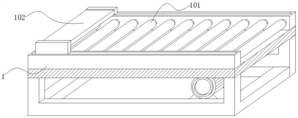
[0034] Embodiment 1: A conveying device in tarpaulin laminating equipment, including a conveyor 1, a roller shaft 101 rotates inside the conveyor 1, a bracket 102 runs through the upper end of the conveyor 1, and the two sides of the bracket 102 slide. The slide bar 103 and the inside of the bracket 102 are provided with a transmission mechanism for automatically collecting dust while smoothing the tarpaulin;
[0035] Wherein: a motor is installed on the side of the conveyor 1 close to the roller shaft 101, the motor is electrically connected to the power supply through a power cord, and the motor and the roller shaft 101 are set together;
[0036] Bracket 102, the bracket 102 and the roller shaft 101 are arranged vertically and correspondingly, the bracket 102 is set in an inverted concave shape, the two sides of the lower end of the bracket 102 are provided with grooves, the grooves are arranged horizontally, and the slide bar 103 slides inside the groove;
[0037] The slidi...
Embodiment 2
[0038] Embodiment 2: with reference to instruction manual Figure 1-4 It can be seen that the difference between Embodiment 2 and Embodiment 1 is that the transmission mechanism includes a support bearing 2, a connecting frame 201, a guide frame 202, a push rod 203, a disk 3 and a fixing frame 301, and the support bearing 2 is hinged inside the bracket 102 The upper end of the connecting frame 201 swings on the lower end of the supporting bearing 2, the guide frame 202 slides on the outside of the connecting frame 201, the push rod 203 is embedded on both sides of the upper end of the guide frame 202, and the disc 3 rotates on the upper end of the push rod 203, The fixed frame 301 is rotatably socketed above the disk 3;
[0039] Wherein: the support bearing 2, the support bearing 2 and the guide frame 202 are vertically correspondingly arranged, and the support bearing 2 and the guide frame 202 swing horizontally at 5-35°;
[0040] The connecting frame 201, the connecting fra...
Embodiment 3
[0046] Embodiment 3: with reference to instruction manual Figure 5-8 It can be seen that the difference between Embodiment 3 and Embodiments 1 and 2 is that the transmission mechanism includes a rotary bearing 4, a gear 401, a tooth piece 1 402, a hinge 403, a baffle plate 404, a connecting rod 5, a telescopic frame 501, and a tooth piece 2 502, inclined plate 503, dust collecting rack 6, rotating shaft 601 and scraper 602, the rotary bearing 4 is hinged in the middle of the lower end of the guide frame 202, the gear 401 rotates on the inner side of the rotary bearing 4, and the gear piece 1 402 surrounds the outer side of the gear 401 , the hinge 403 is hinged on one side of the first gear 402, the baffle 404 swings on one side of the hinge 403, the second gear 502 slides and fits on the upper end of the first gear 402, and the connecting rod 5 slides on the upper end of the second gear 502 The telescopic frame 501 slides and nests on one side of the connecting rod 5, the sw...
PUM
 Abstract
Description
Claims
Application Information
 - R&D
- Intellectual Property
- Life Sciences
- Materials
- Tech Scout
- Unparalleled Data Quality
- Higher Quality Content
- 60% Fewer Hallucinations
Browse by: Latest US Patents, China's latest patents, Technical Efficacy Thesaurus, Application Domain, Technology Topic, Popular Technical Reports.
© 2025 PatSnap. All rights reserved.Legal|Privacy policy|Modern Slavery Act Transparency Statement|Sitemap|About US| Contact US: help@patsnap.com


