
Constant-temperature machine tool

A constant temperature, machine tool technology, used in metal processing machinery parts, maintenance and safety accessories, metal processing equipment, etc., can solve the problems of expensive inert materials, not solving the overall deformation of the machine tool, etc., to solve the problem of temperature rise, avoid the overall deformation effect

Active Publication Date: 2021-01-22
SHENYANG GUANGDA TECH DEV
View PDF14 Cites 0 Cited by
  • Summary
  • Abstract
  • Description
  • Claims
  • Application Information

AI Technical Summary

Problems solved by technology

[0004] However, the above-mentioned first solution does not solve the overall deformation problem of the machine tool with temperature changes, and the second solution does not physically solve the problem of temperature rise, and the price of inert materials is relatively expensive

Method used


Image

  • Constant-temperature machine tool
  • Constant-temperature machine tool

Examples


Embodiment Construction

[0035] In describing the present invention, it should be understood that the terms "center", "longitudinal", "transverse", "length", "width", "thickness", "upper", "lower", "front", " Orientation or position indicated by "back", "left", "right", "vertical", "horizontal", "top", "bottom", "inner", "outer", "clockwise", "counterclockwise", etc. The relationship is based on the orientation or positional relationship shown in the drawings, and is only for the convenience of describing the present invention and simplifying the description, rather than indicating or implying that the referred device or element must have a specific orientation, be constructed and operated in a specific orientation, therefore It should not be construed as a limitation of the present invention.

[0036] In addition, the terms "first" and "second" are used for descriptive purposes only, and cannot be interpreted as indicating or implying relative importance or implicitly specifying the quantity of indic...


PUM


Abstract

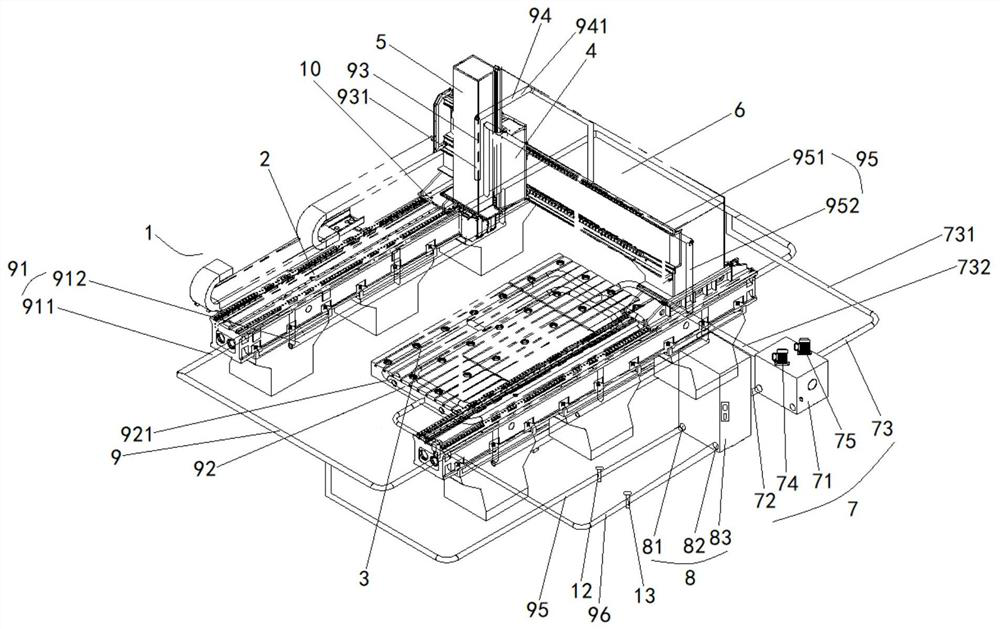
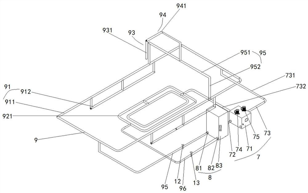
The invention discloses a constant-temperature machine tool, relates to the technical field of machine tools, and mainly aims to perform constant-temperature control on the machine tool, so that the machine tool is always in a constant-temperature state, and overall deformation of the machine tool due to temperature rise is avoided. According to the main technical scheme, the constant-temperaturemachine tool comprises a machine tool body, a workbench, a sliding plate, a ram and a cross beam which are connected with one another, a water tank, a constant-temperature cooling box and a constant-temperature pipeline; the water tank comprises a first tank body, a first water outlet pipeline and a water return pipeline which communicate with one another; the constant-temperature cooling box communicates with the first water outlet pipeline; the constant-temperature pipeline comprises a machine tool body pipeline, a workbench pipeline, a sliding plate pipeline, a ram pipeline and a cross beampipeline which are sequentially arranged in the machine tool body, the workbench, the sliding plate, the ram and the cross beam respectively and communicate with one another; and the machine tool body pipeline, the workbench pipeline, the sliding plate pipeline, the ram pipeline and the cross beam pipeline communicate with the outlet of the constant-temperature cooling box and the water return pipeline. The invention is mainly used for cooling the machine tool.

Description

technical field [0001] The invention relates to the technical field of machine tools, in particular to a constant temperature machine tool. Background technique [0002] A machine tool refers to a machine that manufactures a machine, but any parts that require higher precision and finer surface roughness generally require final processing on the machine tool by cutting. [0003] At present, there are usually two solutions to the accuracy deviation caused by the temperature change of the machine tool. The first is to install the local cooling system of the machine tool, which is only for the high-speed rotating parts, such as the spindle of the boring and milling machine tool, the turntable of the lathe, the chuck, etc.; the second is to use the temperature inert material to control the temperature rise of the spindle For detection and compensation, invar steel or carbon rods are generally used to detect the elongation of the main shaft, and the thermal elongation is compens...

Claims


Application Information

Patent Timeline
IPC IPC(8): B23Q11/12
CPCB23Q11/12
Inventor 秦广财喻鹏
Owner SHENYANG GUANGDA TECH DEV
Learn More