Edge-Lit Backlight Device and Liquid Crystal Display

a backlight device and liquid crystal display technology, applied in semiconductor devices, lighting and heating apparatus, instruments, etc., can solve the problems of adverse effect on the imaging quality of liquid crystal panels, non-uniform temperature distribution, and degradation of light emission efficiency of light sources, so as to prolong the service life of light sources and reduce the effect of heat generation

Active Publication Date: 2012-10-25
TCL CHINA STAR OPTOELECTRONICS TECH CO LTD
View PDF14 Cites 5 Cited by
  • Summary
  • Abstract
  • Description
  • Claims
  • Application Information

AI Technical Summary

Benefits of technology

[0004]An objective of one embodiment of the present disclosure is to provide an edge-lit backlight device and a liquid crystal display (LCD) which can solve the problem caused by the temperature rise of the light source.
[0025]The present disclosure has the following benefits: as compared to the prior art, the edge-lit backlight device and the LCD are simple in structure, allow for regional control functions and can dissipate heat generated by the light sources in a timely and efficient way. This prolongs the service life of the light sources and obviates the problem of degraded imaging quality of the LCD caused by the temperature rise of the light sources.

Problems solved by technology

However, because liquid crystal panels of the LCDs are unable to emit light by themselves, a light source device such as a backlight device must be provided in each of the LCDs.
The temperature rise not only degrades the light emission efficiency of the light source, but also leads to a nonuniform temperature distribution in the LCD which uses the light source to provide back light.
The higher temperature of the LCD near the light source also leads to a reddish color, which has an adverse effect on the imaging quality of the liquid crystal panel.
Moreover, the temperature rise of the light source also shortens the service life of the light source itself significantly.

Method used


Image

  • Edge-Lit Backlight Device and Liquid Crystal Display
  • Edge-Lit Backlight Device and Liquid Crystal Display
  • Edge-Lit Backlight Device and Liquid Crystal Display

Examples


Embodiment Construction

[0031]The present disclosure is more particularly described in the following examples that are intended as illustrative only since numerous modifications and variations therein will be apparent to those skilled in the art.

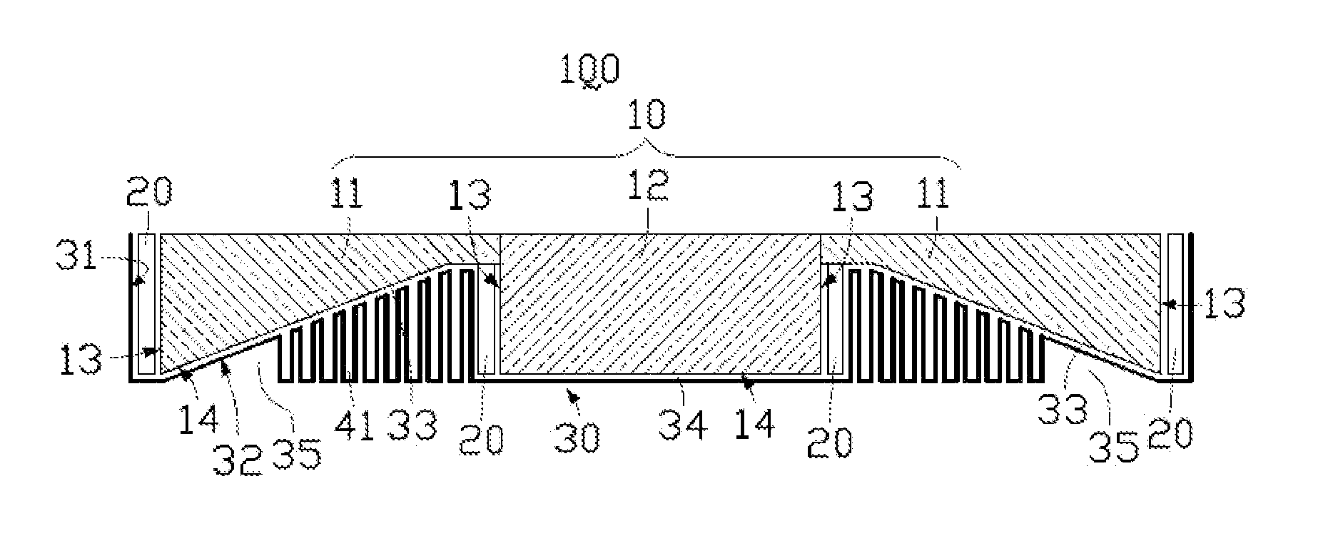
[0032]Referring to FIG. 1, there is shown a schematic structural view of a first embodiment of an edge-lit backlight device according to the present disclosure. The edge-lit backlight device 100 comprises a light guide plate 10, light sources 20, a backplate 30 and heat dissipating elements 41.

[0033]The light guide plate 10 comprises a rectangular plate portion 12 and two wedged plate portions 11 disposed at two sides of the rectangular plate portion 12 respectively. Each of the wedged plate portions 11 has a larger thickness at a side away from the rectangular plate portion 12. The wedged plate portions 11 and the rectangular plate portion 12 each comprise a light incident surface 13 and a bottom surface 14.

[0034]The light sources 20 are disposed adjacent to the l...


PUM

PropertyMeasurementUnit
thicknessaaaaaaaaaa
weightaaaaaaaaaa
driving voltageaaaaaaaaaa

Abstract

An edge-lit backlight device is disclosed in the present disclosure. The edge-lit backlight device comprises a light guide plate, light sources and a backplate. The light guide plate comprises two wedged plate portions and a rectangular plate portion, the two wedged plate portions are disposed at two sides of the rectangular plate portion respectively, and the wedged plate portions and the rectangular plate portion each comprise a light incident surface and a bottom surface. The light sources are disposed adjacent to the light incident surfaces of the wedged plate portions and the rectangular plate portion respectively. A liquid crystal display (LCD) is also disclosed in the present disclosure. The edge-lit backlight device and the LCD of the present disclosure are simple in structure, allow for regional control functions and can dissipate heat generated by the light sources in a timely and efficient way.

Description

FIELD OF THE INVENTION[0001]The present disclosure generally relates to the technical field of liquid crystal displays (LCDs), and more particularly, to an edge-lit backlight device for an LCD and the LCD.BACKGROUND OF THE INVENTION[0002]Liquid crystal displays (LCDs) are a kind of flat panel display device that utilizes liquid crystals to display images. Because of their advantages over other display devices such as lighter weight, thinner profile, lower driving voltage and lower power consumption, the LCDs have found wide application in the industries. However, because liquid crystal panels of the LCDs are unable to emit light by themselves, a light source device such as a backlight device must be provided in each of the LCDs.[0003]In use of a backlight device currently available, a remarkable temperature rise can be found near the light source. The temperature rise not only degrades the light emission efficiency of the light source, but also leads to a nonuniform temperature dist...

Claims


Application Information

Patent Timeline
Patent Type & Authority Applications(United States)
IPC IPC(8): G02F1/1335F21V29/00G09F13/04
CPCF21V29/006F21V29/02F21Y2103/00F21Y2103/003G02F1/133615F21V29/767G02F2001/133628G02B6/0046G02B6/0078G02B6/0085F21Y2101/02F21V29/51F21V29/67F21Y2103/10F21Y2115/10G02F1/133628
Inventor KUO, YI-CHENGZHOU, GEGE
Owner TCL CHINA STAR OPTOELECTRONICS TECH CO LTD
Why Eureka
Try Eureka