Centrifugal compressor bearing, centrifugal compressor and air conditioning system

A centrifugal compressor and bearing center technology, which is applied in the field of centrifugal compressors, bearings for centrifugal compressors, and air-conditioning systems, can solve problems such as lubricating oil temperature rise, bearing life reduction, and reduced lubrication effect, so as to reduce the number of times and increase the number of bearings Life, the effect of increasing the air film stiffness

Active Publication Date: 2013-05-08
GREE ELECTRIC APPLIANCES INC
View PDF3 Cites 4 Cited by
  • Summary
  • Abstract
  • Description
  • Claims
  • Application Information

AI Technical Summary

Problems solved by technology

[0002] At present, the motor shaft of the existing centrifugal compressor is usually supported by a dynamic pressure sliding bearing and lubricated by grease lubricating oil. The disadvantages are: (1) Lubricating oil is used for lubricating, and the speed is relatively low when starting and stopping Under normal circumstances, it is difficult to form an effective oil wedge lubrication between the bearing kinematic pairs, which makes the wear more serious. Although the additional Babbitt bearing bushing is used for motor shaft protection, this also causes the bearing life to be reduced, and the replacement of the bearing The process of lining materials is more complicated and the cost is higher; (2) In addition, in the case of high-speed rotation of the motor shaft, the power loss is large, and the temperature rise of the bearing kinematic pair is also difficult to solve. The temperature rise of the lubricating oil causes its viscosity decrease, which also reduces the lubricating effect

Method used


Image

  • Centrifugal compressor bearing, centrifugal compressor and air conditioning system
  • Centrifugal compressor bearing, centrifugal compressor and air conditioning system
  • Centrifugal compressor bearing, centrifugal compressor and air conditioning system

Examples


Embodiment 1

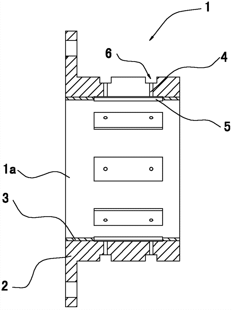
[0029] Such as figure 1 As shown, a bearing 1 for a centrifugal compressor includes a bearing bush 2 and a bearing bush 3 disposed on the inner surface of the bearing bush 2, and the material of the bearing bush 3 is engineering ceramic material. The center of the bearing 1 has a center hole 1a. The bearing 1 is processed with two rows (8 in each row) of radially penetrating air supply holes 4 arranged at equal intervals along the circumferential direction. On the inner wall of the bearing, eight air cavities 5 are arranged at equal intervals in the circumferential direction, and the air cavities 5 are rectangular grooves. It can be seen from the figure that the outlets of the eight air supply holes 4 in each row are respectively located in the eight air cavities 5 . Since the air supply holes 4 and the air cavities 5 are arranged at equal intervals along the bearing circumference, and the number of outlets of the air supply holes 4 in each air cavity 5 is the same, it can e...

Embodiment 2

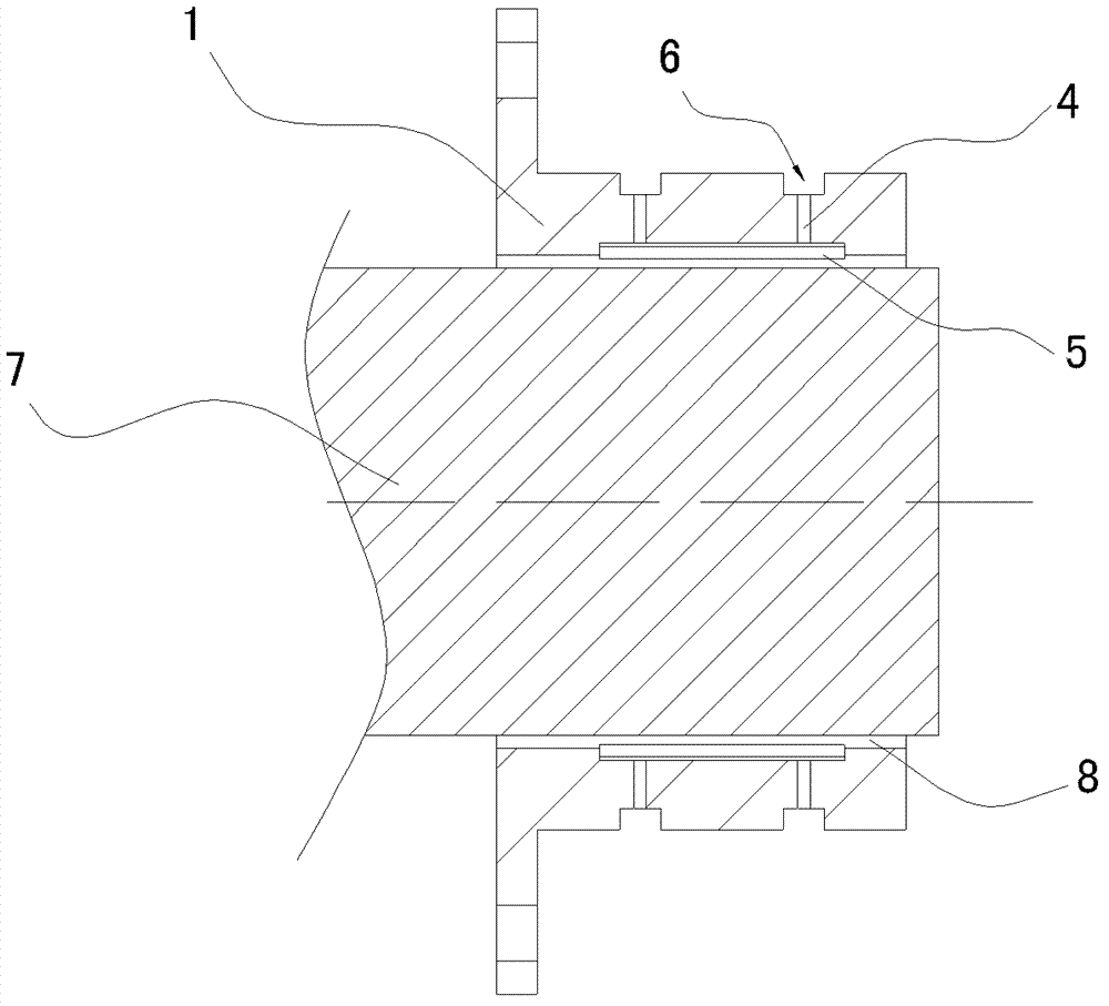
[0039] Such as image 3 As shown, the difference from Embodiment 1 is that a row of radially penetrating air supply holes 4 arranged at equal intervals in the circumferential direction is processed on the bearing 1 . Compared with the bearing in embodiment 1, the bearing in this embodiment has a simpler structure and is easier to process.

Embodiment 3

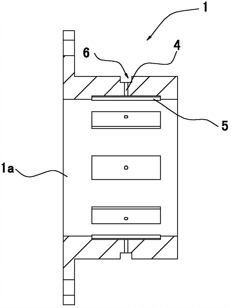
[0041] Such as Figure 4 As shown, the difference from Embodiment 1 is that three rows of radially penetrating air supply holes 4 arranged at equal intervals in the circumferential direction are processed on the bearing 1 . Compared with the bearing of Embodiment 1, the bearing of this embodiment can ensure a more uniform axial bearing capacity for the journal.


PUM


Abstract

The invention discloses a centrifugal compressor bearing with the center provided with a central hole. At least one row of gas supply holes are peripherally arranged on the bearing and communicated with the central hole, and gas chambers are arranged on the inner wall of the bearing at outlets of the gas supply holes. The centrifugal compressor bearing utilizes high-pressure gaseous refrigerant led out from a condenser to lubricate bearing kinematic pairs at two ends of a motor shaft, so that a compressor can simultaneously adapt to operations at extremely high speed and extremely low speed, operating range is enlarged, the refrigerant is utilized for cooling the bearing kinematic pairs, the problem of temperature rising of the bearing kinematic pairs is solved thoroughly, and operating stability is improved. Besides, the invention further discloses a centrifugal compressor using the bearing and an air conditioning system using the bearing.

Description

technical field [0001] The invention relates to a bearing, especially a bearing for a centrifugal compressor, a centrifugal compressor using the bearing, and an air-conditioning system using the bearing. Background technique [0002] At present, the motor shaft of the existing centrifugal compressor is usually supported by a dynamic pressure sliding bearing and lubricated by grease lubricating oil. The disadvantages are: (1) Lubricating oil is used for lubricating, and the speed is relatively low when starting and stopping Under normal circumstances, it is difficult to form an effective oil wedge lubrication between the bearing kinematic pairs, which makes the wear more serious. Although the additional Babbitt bearing bushing is used for motor shaft protection, this also causes the bearing life to be reduced, and the replacement of the bearing The process of lining materials is more complicated and the cost is higher; (2) In addition, in the case of high-speed rotation of th...

Claims


Application Information

Patent Timeline
Patent Type & Authority Applications(China)
IPC IPC(8): F04D29/056
Inventor 张治平刘华李宏波钟瑞兴王晨光蒋楠谢蓉蒋彩云傅鹏闫秀兵
Owner GREE ELECTRIC APPLIANCES INC
Why Eureka
Try Eureka