Supercharge Your Innovation With Domain-Expert AI Agents!

Rail train traction control system

A traction control system and a technology for rail trains, applied in the field of train traction, can solve problems such as the absence of wheels, insufficient friction, and movement of the traction device, and achieve the effects of good braking, simple braking steps and strong linkage

Inactive Publication Date: 2022-04-12
罗亚
View PDF1 Cites 1 Cited by
  • Summary
  • Abstract
  • Description
  • Claims
  • Application Information

AI Technical Summary

Problems solved by technology

[0003] Although the existing technology can realize the transportation of coal mines, there is no device for emergency braking of the wheels in the traction device in the prior art. When the car body trips, it cannot be stopped in time, and only the tractor Due to its own weight, when unloading coal mines, the friction between the traction device and the ground may be insufficient due to too many coal mines, which will cause the traction device to move and affect the unloading of coal mines.
[0004] A rail transit train traction control system equipment with application number 202010155037.7 solves the problem that the car body cannot be stopped in time when the car body trips in the prior art, and the second threaded rod is driven by the second motor to rotate, and the second threaded rod Drive the second gear to rotate, the second gear drives the connecting rod to move, so that the connecting rod drives the circular block to move, and the circular block drives the tooth rod to move, which solves the friction between the traction device and the ground in the prior art Insufficient problem
[0005] The traction equipment described above still has many deficiencies in the process of use. For example, when the traction equipment is stopped, it is divided into two steps. One is to pull the handle to slow down, and the other is to start the second The motor is used to avoid the movement of the car body during unloading, which is more cumbersome to operate

Method used


Image

  • Rail train traction control system
  • Rail train traction control system
  • Rail train traction control system

Examples


Embodiment Construction

[0028] The following will clearly and completely describe the technical solutions in the embodiments of the present invention with reference to the accompanying drawings in the embodiments of the present invention. Obviously, the described embodiments are only some, not all, embodiments of the present invention. Based on the embodiments of the present invention, all other embodiments obtained by persons of ordinary skill in the art without creative efforts fall within the protection scope of the present invention.

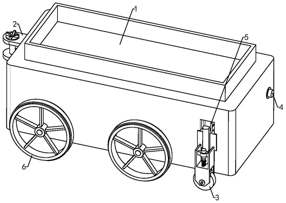
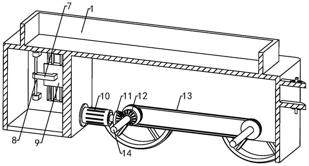
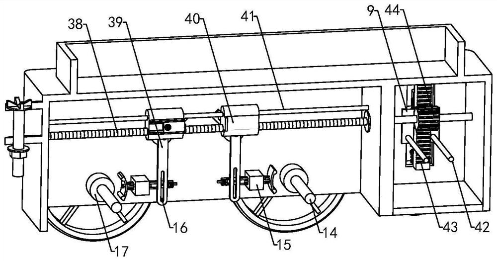
[0029] see Figure 1-6 , the present invention provides a technical solution:

[0030] A rail train traction control system, comprising a tractor 1, a hook assembly 2, a transmission shaft 14, and rollers 6 installed at both ends of the transmission shaft 14, the above is the disclosed prior art, and will not be described in detail here. There is a power part that drives the transmission shaft 14 to rotate, and the transmission shaft 14 is equipped with a friction...


PUM


Abstract

The invention discloses a traction control system for a rail train. The traction control system comprises a tractor, a hook assembly, a transmission shaft and rolling wheels installed at the two ends of the transmission shaft. In the application, when the tractor is braked, a motor I drives a screw rod to rotate, a moving block drives a bulge to move in a through groove II, a rotating arm rotates, a moving pin moves in a through groove I, and the moving pin drives a threaded sleeve and a screw rod to move, so that a clamping plate is in contact with a friction block I, the speed of the tractor is reduced, and meanwhile, under the action of a toothed plate and a gear, the friction block I is driven to rotate; in the process that the sliding block drives the support and the limiting wheel to move downwards, the limiting wheel makes contact with the rail, the elastic telescopic piece is compressed due to stress, and the sliding block drives the sliding piece to move, the current input into the electromagnet is increased, and under the repelling effect of the electromagnet and the magnet, the second friction block makes contact with the limiting wheel, and the braking effect is achieved. All the components are high in linkage, and the braking step is simpler.

Description

technical field [0001] The invention relates to the technical field of train traction, in particular to a rail train traction control system. Background technique [0002] In addition to carrying people, rail transit can also carry goods, such as coal. With the continuous increase of coal production capacity, major coal enterprises have adopted comprehensive mechanized coal mining equipment and technology, and the electronic control system of working face equipment is concentrated in On the equipment train of the return air or transportation lane, it moves forward as the fully mechanized mining advances. [0003] Although the existing technology can realize the transportation of coal mines, there is no device for emergency braking of the wheels in the traction device in the prior art. When the car body trips, it cannot be stopped in time, and only the tractor Due to its own weight, when unloading coal mines, the friction between the traction device and the ground may be ins...

Claims


Application Information

Patent Timeline
Patent Type & Authority Applications(China)
IPC IPC(8): B61H5/00B61H7/04B61H13/20B61H15/00
Inventor 罗亚
Owner 罗亚
Features
  • R&D
  • Intellectual Property
  • Life Sciences
  • Materials
  • Tech Scout
  • Unparalleled Data Quality
  • Higher Quality Content
  • 60% Fewer Hallucinations
Learn More