Gas burner

A gas burner, gas technology, applied in the direction of gas fuel burner, burner, combustion method, etc., can solve the problems of increasing the final cost of the burner, expensive cooling system, etc.

Pending Publication Date: 2022-04-12
POLIDORO
View PDF6 Cites 0 Cited by
  • Summary
  • Abstract
  • Description
  • Claims
  • Application Information

AI Technical Summary

Problems solved by technology

However, this cooling system is very expensive and seriously increases the final cost of the burner

Method used


Image

  • Gas burner
  • Gas burner
  • Gas burner

Examples


Embodiment Construction

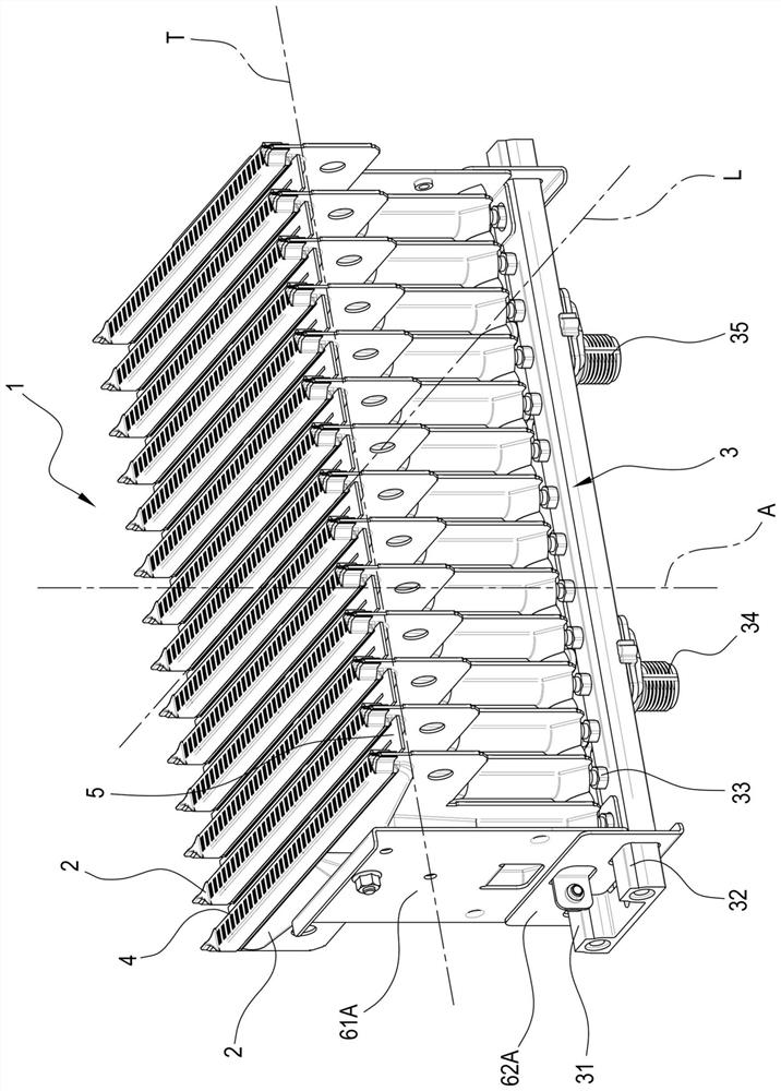
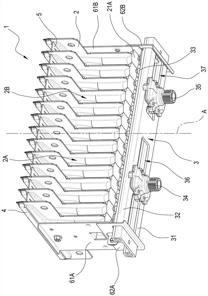
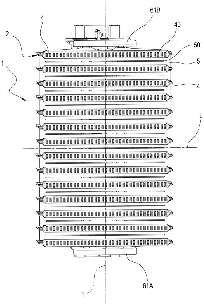
[0041] For the purposes of this disclosure, reference numeral 1 denotes a burner. The burner 1 comprises a plurality of ramp-shaped elements 2 . The ramp-like elements 2 are oriented along respective planes of extension parallel to the longitudinal direction L and the air intake direction A. As shown in FIG. The air intake direction A is at right angles to the longitudinal direction L. The ramp-like elements 2 are arranged side by side along the transverse direction T. As shown in FIG. The transverse direction T is at right angles to the longitudinal direction L and the direction A of the air intake.

[0042]Each ramp-like element 2 comprises a first intake duct 21 and a second intake duct 22 . The first intake duct 21 and the second intake duct 22 are shaped as Venturi tubes, that is to say they comprise a converging part and a diverging part downstream of the converging part. The first intake duct 21 and the second intake duct 22 have respective inlets 21A, 22A and respe...


PUM


Abstract

An air-cooled gas burner (1) comprises: a plurality of ramp-like elements (2), each comprising a first intake duct (21) and a second intake duct (22) having respective inlets (21A, 22A) and respective outlets (21B, 22B), where the plurality of ramp-like elements (2) are arranged contiguously along a transverse direction (T); a manifold (3) configured to supply gas to the inlets of the first (21) and second (22) intake ducts, where the first (21) and second (22) intake ducts are configured to draw gas and primary air into their respective inlets (21A, 22A) by Venturi effect; a respective diffuser (4) for each ramp-like element (2) defining a plurality of holes (40) from which flames are generated by combustion of gases from the first (21) and second (22) intake ducts.

Description

technical field [0001] The invention relates to a gas burner and a method of burning gas. Background technique [0002] In particular, the burner of the present invention is suitable for use in boilers and water heaters. Burners are known in the art comprising a plurality of elements (or ramps or plates) arranged parallel to each other and defining inside them ducts into which gas is supplied by means of a manifold located at the first end of the elements . Gas is drawn into the duct along with air (called primary air) and reaches the second end (or head) of the element where there is a diffuser through which the gas creates a flame that propagates into the combustion chamber. Burners are known in the prior art in which each element (or ramp or plate) defines two ducts configured to draw primary air and gas in parallel; It is particularly advantageous with regard to the heat flux generated in the combustion chamber. Examples of burners with two intake ducts are described...

Claims


Application Information

Patent Timeline
IPC IPC(8): F23D14/02F23D14/58F23D14/60F23D14/46
CPCF23D14/045F23D14/64F23D2900/14641
Inventor 多梅尼科·佩塞里科瓦尔特·卡瓦索彼得罗·帕利亚罗
Owner POLIDORO
Why Eureka
Try Eureka