
Filtering device and lampblack purifier

A lampblack purifier and filter device technology, which is applied in the fields of lampblack removal, household heating, lighting and heating equipment, etc., can solve the problems of affecting the purification effect of lampblack purifiers and the inability to purify pretreated gas, achieving good purification effect and slowing down effect of speed

Pending Publication Date: 2022-04-12
HANGZHOU ROBAM APPLIANCES CO LTD
View PDF0 Cites 0 Cited by
  • Summary
  • Abstract
  • Description
  • Claims
  • Application Information

AI Technical Summary

Problems solved by technology

[0005] In order to ensure the centrifugal separation effect of the oil fume, it is usually necessary to make the flow velocity of the oil fume in the centrifugal separation mechanism as fast as possible, so that the flow velocity of the pretreatment gas discharged from the outlet into the purifier body is too fast, so that the pretreatment gas cannot flow in the purifier body. Sufficient purification in the interior will affect the overall purification effect of the oil fume purifier

Method used


Image

  • Filtering device and lampblack purifier
  • Filtering device and lampblack purifier
  • Filtering device and lampblack purifier

Examples


Embodiment 1

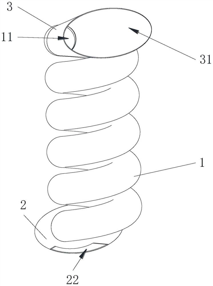
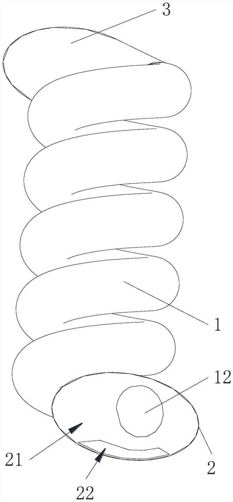
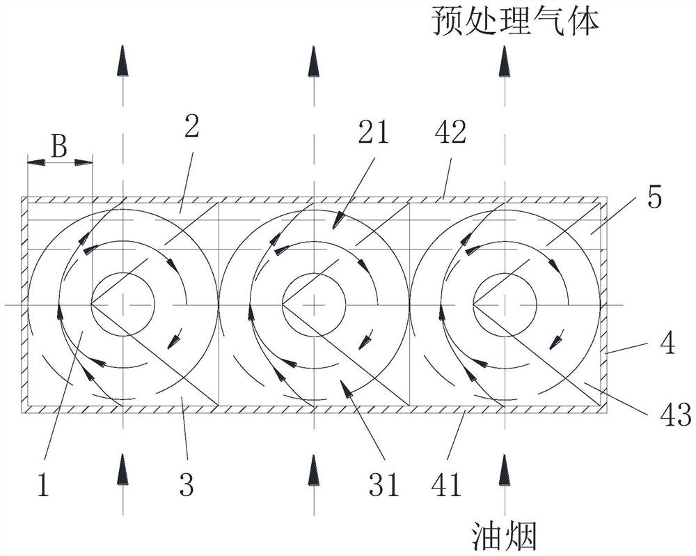
[0049] Such as figure 1 with figure 2 As shown, this embodiment provides a filter device, which is usually used in a fume purifier and is arranged upstream of the purifier body. The filter device plays a pre-filtering effect on the fume. The mechanism 1 includes an inlet 11 and an outlet 12 , the separation mechanism 1 can separate the oily fume entering from the inlet 11 , and the relatively clean pretreatment gas separated from the oily fume is discharged from the outlet 12 .

[0050] The separation mechanism 1 in the prior art usually adopts a mesh or honeycomb mechanical filter, which can filter large oil droplets and large particles in the oil fume. It reduces the resistance of the oil fume purifier by about 80%, increases the load of the fan, affects the overall purification efficiency of the oil fume purifier, and increases the frequency of maintenance and cleaning of the oil fume purifier.

[0051] In order to solve the above problems, such as figure 1 with figur...

Embodiment 2

[0086] This embodiment also provides an oil fume purifier, which includes a casing, a purifier body and the filter device in Embodiment 1. An air duct is opened on the cabinet, and the filter device and the purifier body are arranged in the air duct along the The flow direction of the oil fume is arranged, and the oil fume can pass through the filter device and the oil fume purifier in sequence through the external fan to form a clean gas and be discharged through the pipeline. The filter device can remove large particles of oil fume and particulate matter, and the purifier body can perform further secondary filtration on the pretreated gas filtered by the filter device, so as to achieve better oil fume filtering effect of the oil fume purifier.

[0087] The oil fume purifier in this embodiment can avoid the excessive flow rate of the pretreatment gas discharged from the outlet 12 by applying the filter device of the first embodiment, ensure that the pretreatment gas is fully p...


PUM


Abstract

The invention discloses a filtering device and an oil fume purifier, and relates to the field of catering. The filtering device comprises a separation mechanism and an air outlet pipe, the separation mechanism comprises an inlet and an outlet, lampblack entering from the inlet is separated by the separation mechanism to form pretreated gas, the pretreated gas is discharged from the outlet, the air outlet pipe is connected with the separation mechanism, and a first channel communicated with the outlet is formed in the air outlet pipe. The cross sectional area of the first channel is gradually increased in the discharge direction of the pretreated gas, and the first channel of the structure can reduce the flow speed of the discharged pretreated gas so as to ensure the good purification effect of the whole oil smoke purifier. The oil fume purifier can achieve a good purification effect on oil fume by applying the filtering device.

Description

technical field [0001] The invention relates to the field of catering, in particular to a filter device and a smoke oil purifier. Background technique [0002] At present, with the continuous enhancement of people's awareness of environmental protection, oil fume purifiers have become a necessity in the catering industry. Generally, oil fume purifiers are electrostatic oil fume purifiers, activated carbon purifiers, UV purifiers, etc. [0003] Among them, the electrostatic oil fume purifier uses the principle of high-voltage electrostatic to remove oil fume or particulate matter. The electrostatic oil fume purifier includes a casing, a filter device, and a purifier body that adopts electrostatic treatment. Arranged sequentially in the air duct along the flow direction of oil fume, through the external fan, the oil fume can pass through the filter device and the oil fume purifier in turn to form clean gas and be discharged through the pipe, wherein the casing and the fan are ...

Claims


Application Information

Patent Timeline
IPC IPC(8): F24C15/20
Inventor 任富佳陈尼青费本开黄一丁
Owner HANGZHOU ROBAM APPLIANCES CO LTD
Learn More