Sighting telescope

A technology of sight and mirror body, applied in the field of sight, can solve the problems of included angle, unable to reflect the distance value, etc., and achieve the effect of convenient ballistic and wind deflection.

Inactive Publication Date: 2022-04-12
HUBEI HUAZHONG PHOTOELECTRIC SCI & TECH
View PDF8 Cites 0 Cited by
  • Summary
  • Abstract
  • Description
  • Claims
  • Application Information

AI Technical Summary

Problems solved by technology

[0003] However, when the existing scope is adjusted to the left and right and the height position of the mirror body, the optical axis of the mirror body (that is, the optical axis of the correction mirror tube group) and the position of the laser range finder are also changing, resulting in the adjustment of the mirror body. There is an angle between the optical axis and the optical axis of the laser rangefinder, so it is necessary to repeatedly adjust the laser rangefinder to make it parallel to the optical axis of the mirror body, so as to avoid the results obtained by the laser rangefinder from not reflecting the real distance. value

Method used


Image

  • Sighting telescope
  • Sighting telescope
  • Sighting telescope

Examples


Embodiment Construction

[0029] In order to make the object, technical solution and advantages of the present invention clearer, the present invention will be further described in detail below in conjunction with the accompanying drawings and embodiments. It should be understood that the specific embodiments described here are only used to explain the present invention, not to limit the present invention. In addition, the technical features involved in the various embodiments of the present invention described below can be combined with each other as long as they do not constitute a conflict with each other.

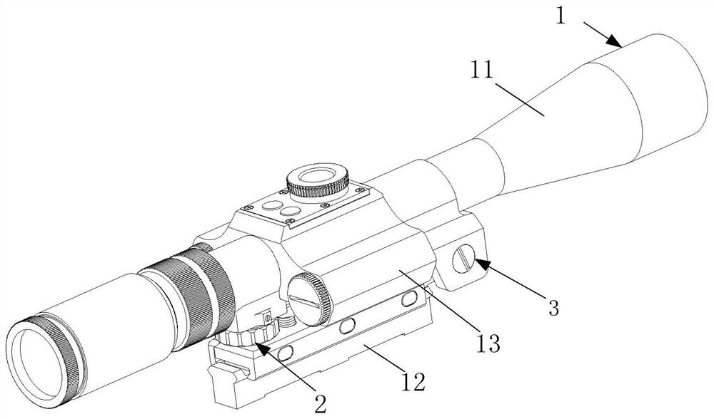
[0030] figure 1 It is a structural schematic diagram of a scope provided by an embodiment of the present invention, such as figure 1 As shown, the scope includes a body assembly 1 , a ballistic adjustment assembly 2 and a windage adjustment assembly 3 .

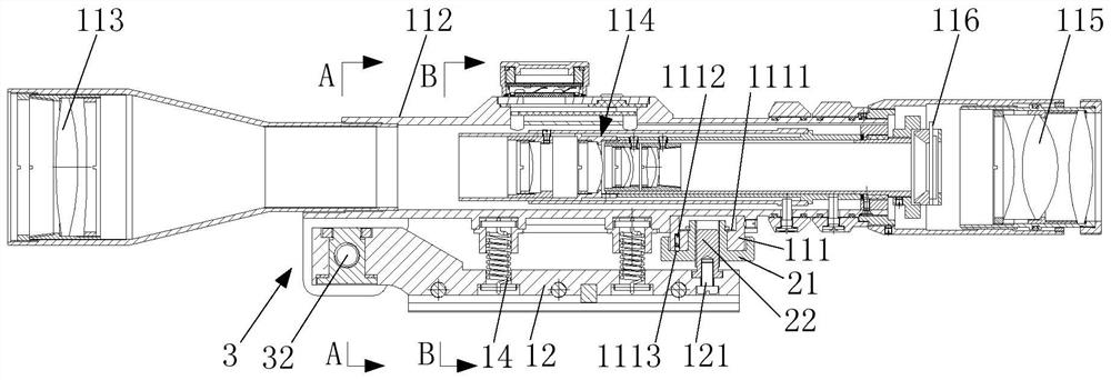
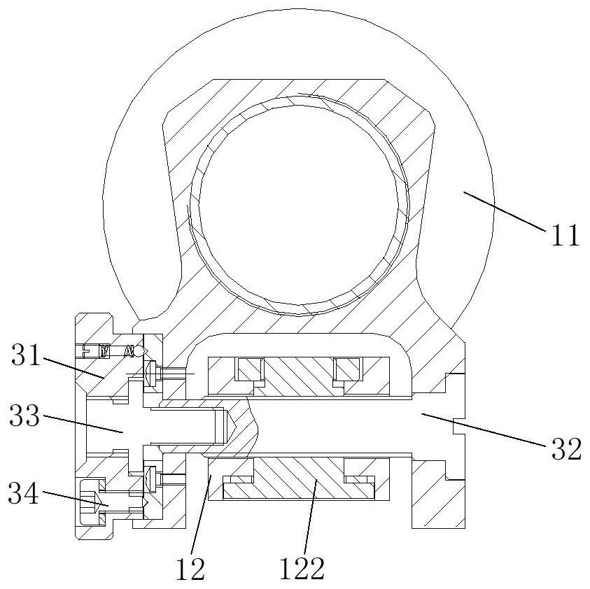
[0031] The body assembly 1 includes a mirror body 11 , a support 12 and a laser range finder 13 , the mirror body 11 is located above the su...


PUM


Abstract

The invention discloses a sighting telescope, and belongs to the technical field of sighting telescopes. The sighting telescope comprises a body assembly, a trajectory adjusting assembly and a windage yaw adjusting assembly. The body assembly comprises a mirror body, a support and a laser range finder, and the laser range finder is located on the mirror body. The ballistic adjusting assembly comprises a ballistic adjusting knob and a ballistic adjusting screw, the ballistic adjusting knob is rotatably arranged at one end of the mirror body, and one end of the ballistic adjusting screw is fixed to the support. The windage yaw adjusting assembly comprises a windage yaw adjusting knob and a windage yaw adjusting screw, the windage yaw adjusting knob coaxially sleeves one end of the windage yaw adjusting screw, the windage yaw adjusting screw horizontally penetrates through the support and is in threaded fit with the support, and the other end of the windage yaw adjusting screw is rotatably inserted into the other end of the mirror body. According to the sighting telescope provided by the invention, the ballistic trajectory and windage yaw of the sighting telescope can be corrected, and the problem that an included angle is formed between the optical axis of the sighting telescope and the optical axis of the laser range finder in the correction process is solved.

Description

technical field [0001] The invention belongs to the technical field of scopes, and more specifically relates to a scope. Background technique [0002] The mirror body of an optical sight has at least three optical lens groups, which are respectively an objective lens group, a correction lens tube group and an eyepiece group. The objective lens group is responsible for collecting light. When the objective lens group is larger, the scene in the scope should be brighter. The eyepiece group is responsible for converting these light rays back to parallel rays, so that the eyes can focus and create the largest field of view; while the correction lens group is Correct the image of the objective lens from upside down and left to right to the correct direction, and is responsible for adjusting the magnification. [0003] However, when the existing scope is adjusted to the left and right and the height position of the mirror body, the optical axis of the mirror body (that is, the opt...

Claims


Application Information

Patent Timeline
Patent Type & Authority Applications(China)
IPC IPC(8): F41G1/14F41G1/26F41G1/473F41G11/00
Inventor 冯清胡瀚李利华
Owner HUBEI HUAZHONG PHOTOELECTRIC SCI & TECH
Why Eureka
Try Eureka