Eureka AIR delivers breakthrough ideas for toughest innovation challenges, trusted by R&D personnel around the world.

Fiber grating sensor and deep roadway surrounding rock strain monitoring method and system

A technology of fiber grating and monitoring system, which is applied in the transmission of sensing components, instruments, measuring devices and other directions using optical devices, can solve the problems of high cost of monitoring equipment, complicated operation of monitoring methods, and inability to monitor the deformation process of surrounding rocks.

Active Publication Date: 2022-04-12
INST OF ROCK & SOIL MECHANICS CHINESE ACAD OF SCI
View PDF5 Cites 0 Cited by
  • Summary
  • Abstract
  • Description
  • Claims
  • Application Information

AI Technical Summary

Problems solved by technology

[0005] However, in the research process of the existing related technologies, the inventors found that the currently used monitoring method for the deformation of the surrounding rock in the deep coal mine roadway cannot be compared with other reasons due to the cumbersome operation of the monitoring method itself, the high cost of monitoring equipment, and the scope of application. To monitor the deformation process of the surrounding rock well, that is to say, there is a problem that the monitoring accuracy of the deformation of the surrounding rock in the deep coal mine roadway is not high

Method used


Image

  • Fiber grating sensor and deep roadway surrounding rock strain monitoring method and system
  • Fiber grating sensor and deep roadway surrounding rock strain monitoring method and system
  • Fiber grating sensor and deep roadway surrounding rock strain monitoring method and system

Examples


Embodiment Construction

[0051] The following will clearly and completely describe the technical solutions in the embodiments of the application with reference to the drawings in the embodiments of the application. Apparently, the described embodiments are only some of the embodiments of the application, not all of them. Based on the embodiments in this application, all other embodiments obtained by those skilled in the art without making creative efforts belong to the scope of protection of this application.

[0052] The terms "first", "second" and the like in the specification and claims of the present application and the above drawings are used to distinguish similar objects, and are not necessarily used to describe a specific sequence or sequence. It is to be understood that the terms so used are interchangeable under appropriate circumstances such that the embodiments described herein can be practiced in sequences other than those illustrated or described herein. Furthermore, the terms "comprisin...


PUM

PropertyMeasurementUnit
wavelengthaaaaaaaaaa
reflectanceaaaaaaaaaa

Abstract

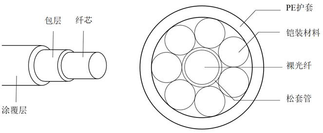
The invention provides a fiber bragg grating sensor, a deep roadway surrounding rock strain monitoring method and a deep roadway surrounding rock strain monitoring system, is used for monitoring deformation of deep roadway surrounding rock, and provides a weak fiber bragg grating array wide-range strain sensor which can accurately monitor strain of the deep roadway surrounding rock. The fiber bragg grating sensor comprises an optical fiber, the optical fiber comprises an optical fiber core and a plurality of fiber bragg gratings recorded on the optical fiber core, the fiber bragg gratings are weak fiber bragg gratings with the peak reflectivity lower than 1%, and the multiple fiber bragg gratings conduct unit discretization on the whole optical fiber to achieve quasi-distributed sensing. In the working process, after incident light enters the sensing network, composed of the fiber bragg gratings, of the optical fiber and has a reflection phenomenon, a part of light waves meeting the Bragg Bragg grating condition wavelength can be reflected back, the remaining light waves can be continuously transmitted to the next grating along the fiber core of the optical fiber, and through multiple times of reflection in the optical fiber and demodulation of the reflected light, the light waves with the wavelength meeting the Bragg Bragg grating condition wavelength can be obtained. And the sensing function of the optical fiber sensing network is realized.

Description

technical field [0001] The present application relates to the field of coal mining, in particular to an optical fiber grating sensor, a strain monitoring method and system for surrounding rock in deep roadways. Background technique [0002] At present and for a long time in the future, coal is still the main energy source in our country. Underground mining is the main method of mining deep coal resources. A large number of roadways need to be excavated underground. After the roadway is excavated, the stress of the surrounding rock will be adjusted. If the concentrated stress exceeds the strength of the surrounding rock, the surrounding rock near the surface of the roadway will be destroyed first, and gradually Deep expansion until the three-dimensional stress balance is reached at a certain depth, at which point the surrounding rock has transformed into a broken state. [0003] Under the influence of three highs and one disturbance for a long time, the surrounding rock mass...

Claims


Application Information

Patent Timeline
Patent Type & Authority Applications(China)
IPC IPC(8): G01B11/16G01K11/3206G01D5/26
CPCG01L1/246G01M5/0033
Inventor 刘滨康永水朱元广刘学伟王升耿志
Owner INST OF ROCK & SOIL MECHANICS CHINESE ACAD OF SCI
Why Eureka
Eureka Blog
Learn More