
Brillouin optical fiber sensing system strain calibrating device and method

A technology of optical fiber sensing system and calibration device, which is applied in the direction of adopting optical devices, measuring devices, instruments, etc., can solve the problems affecting the demodulation accuracy of strain variables, etc., and achieve small damage to optical fibers, high detection efficiency, and simple and easy-to-operate detection methods Effect

Pending Publication Date: 2018-08-03
CHINA JILIANG UNIV
View PDF7 Cites 5 Cited by
  • Summary
  • Abstract
  • Description
  • Claims
  • Application Information

AI Technical Summary

Problems solved by technology

[0004] The present invention aims at the inaccurate calculation of the strain-frequency shift coefficient caused by the inability to directly obtain the strain of the optical fiber in the prior art, thereby affecting the demodulation accuracy of the strain of the Brillouin optical fiber sensing system. The purpose of the present invention is to develop a set of The strain calibration device and calibration method of the Brillouin optical fiber sensing system, by applying a known standard strain to the optical fiber, combined with the Brillouin optical fiber sensing system to obtain the frequency shift of the Brillouin scattered light signal in the optical fiber, and then obtain the strain-frequency shift coefficient, and then realize the calibration of the strain parameter of the optical fiber sensing device

Method used


Image

  • Brillouin optical fiber sensing system strain calibrating device and method
  • Brillouin optical fiber sensing system strain calibrating device and method
  • Brillouin optical fiber sensing system strain calibrating device and method

Examples


Embodiment Construction

[0018] The present invention will be further described below in conjunction with accompanying drawing.

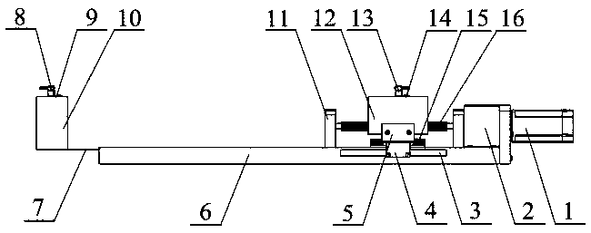
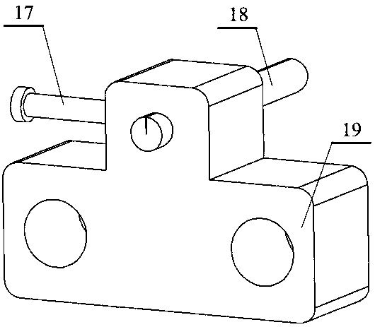
[0019] Such as figure 1 with 2 As shown, the fiber holders 8, 13 are respectively placed on the fixture table 10 and the moving slider 12 through the fiber holder fixing parts 9, 14, and are used to fix the bare fiber, so that the bare fiber to be tested is under a certain pre-tension state, the initial length l of the bare optical fiber to be tested is equal to the length between the ends of the fixed rods of the two optical fiber holders. The fixture table 10 is fixed on the movable base 7, and the distance between the fixture table 10 and the fixed base 6 can be changed by moving the base 7 to meet the requirements of measuring the strain of single-mode bare optical fibers with different lengths. The height of the upper surface of the fixture table 10 and the movable slider 12 is consistent And always fixed, the servo motor 1 and the reducer 2 are fixed on the fixed ba...


PUM


Abstract

The invention discloses a Brillouin optical fiber sensing system strain calibrating device and method. A ball screw is driven by a servo motor to rotate, a moving slider which is fixed to a guide railis made to do horizontal motion, and then single-mode bare optical fibers which are fixed to the moving slider are made to generate strain displacement; the optical fiber strain displacement is readthrough a grating ruler, and by comparing a reading value with a preset value, after the reading value reaches a deceleration range, a controller controls the servo motor to gradually slow down untilthe speed finally reaches the preset displacement value. It is achieved that the known constant strain is applied to the optical fibers, the amount of frequency shift of a Brillouin scattered light signal in the optical fibers is obtained by combining a Brillouin optical fiber sensing system, it is achieved that a strain-frequency shift coefficient is calibrated, and it also can be achieved that the strain parameter of the Brillouin optical fiber sensing system is calibrated. Compared with the prior art, the device is simple in structure and convenient to operate, and has the advantages of being high in positioning precision, parallelism and straightness, and low in backlash.

Description

technical field [0001] The invention relates to a calibration device and a calibration method suitable for a coal mine optical fiber sensing type safety monitoring system, in particular to a strain calibration device and a calibration method based on a Brillouin optical fiber sensing system. Background technique [0002] At present, optical fiber sensing technologies mainly include: Rayleigh scattering, Raman scattering and Brillouin scattering; Rayleigh scattering optical fiber sensing technology can only measure the loss and breakpoint of the optical fiber, but cannot measure physical quantities such as temperature and strain. Optical fiber sensing based on the principle of Mann scattering is one of the most mature technologies in distributed optical fiber sensing. The optical signal of Raman scattering is relatively weak, so it is difficult to detect, and it is only sensitive to temperature, so it is difficult to be used in applications that require stress detection. Geol...

Claims


Application Information

Patent Timeline
Patent Type & Authority Applications(China)
IPC IPC(8): G01B11/16
CPCG01B11/165
Inventor 胡佳成曹鹏飞王梓鉴颜迪新刘泽国
Owner CHINA JILIANG UNIV
Learn More