Space optical communication miniaturized terminal static aberration correction method

A space optical communication and aberration correction technology, applied in optics, optical components, sustainable communication technology, etc., can solve problems such as poor spot quality and unfavorable tracking function, and achieve the effect of eliminating static aberration and improving spot quality

Active Publication Date: 2022-04-12
ZHEJIANG LAB +1
View PDF8 Cites 0 Cited by
  • Summary
  • Abstract
  • Description
  • Claims
  • Application Information

AI Technical Summary

Problems solved by technology

[0003] The purpose of the present invention is to solve the problem that the initial aberration of the CCP light path and the beacon light receiving light path in the prior art is relatively poor, which will lead to poor spot quality of the beacon light received by the CCD, which is not conducive to the realization of the tracking function. Static aberration correction method for common optical path and beacon light receiving optical path of space optical communication miniaturized terminal

Method used


Image

  • Space optical communication miniaturized terminal static aberration correction method
  • Space optical communication miniaturized terminal static aberration correction method
  • Space optical communication miniaturized terminal static aberration correction method

Examples


specific Embodiment approach 1

[0018] Specific implementation mode one: refer to figure 1 Specifically explain this embodiment, the method for correcting static aberration of a miniaturized terminal for spatial optical communication described in this embodiment, the method includes:

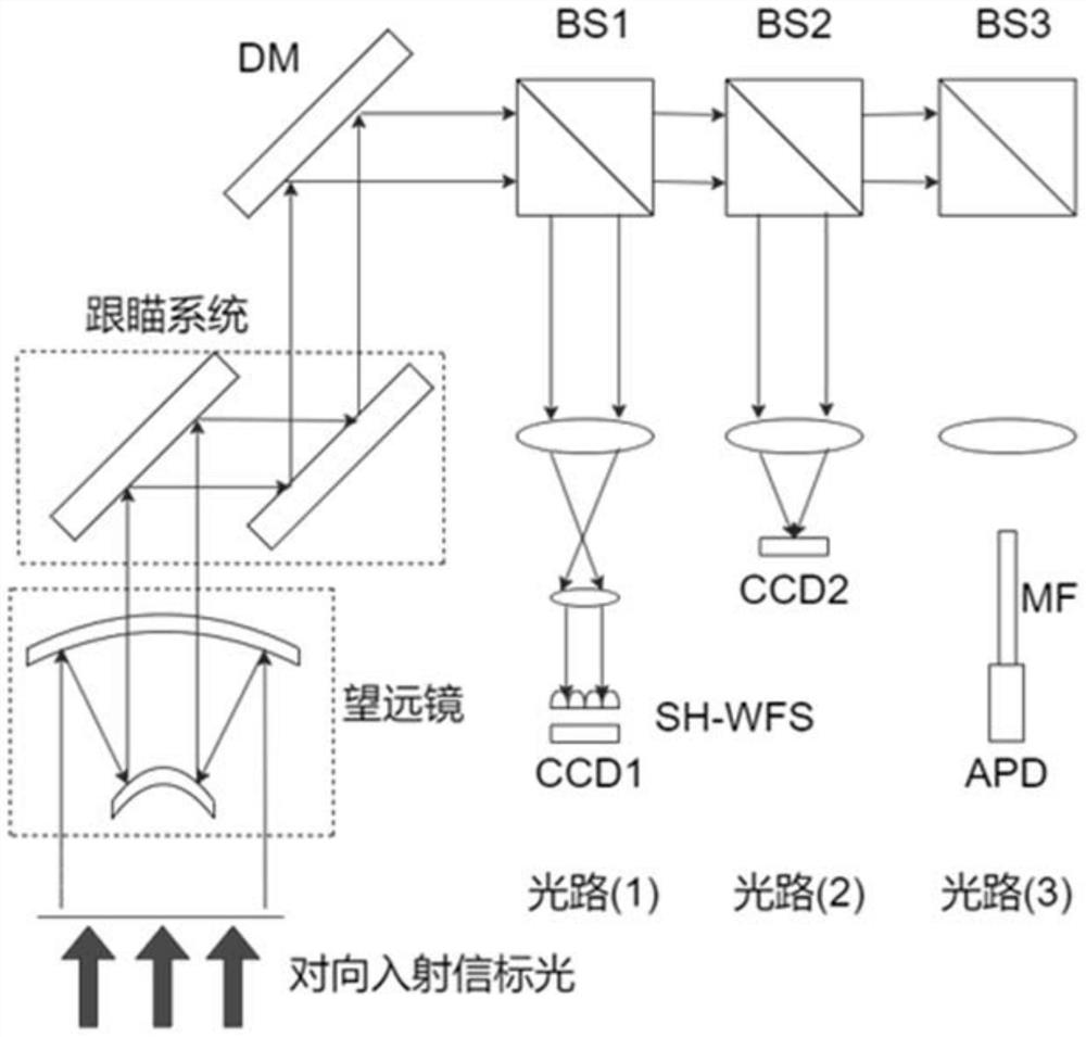
[0019] Step 1: Build an all-optical path module, the all-optical path system includes three light paths:

[0020] Optical path 1: The incident beacon light passes through the telescope, the tracking system and the piezoelectric deformable mirror in turn. After passing through the piezoelectric deformable mirror, the beacon light passes through the first beam splitter and then shrinks the beam. After the beam shrinks, it enters the Shaker-Hart Man wave front detector;

[0021] Optical path 2: The incident light passes through the telescope, the tracking system and the piezoelectric deformable mirror in sequence. The beacon light after passing through the piezoelectric deformable mirror passes through the first beam splitter an...

specific Embodiment approach 2

[0025] Embodiment 2: This embodiment is a further description of Embodiment 1. The difference between this embodiment and Embodiment 1 is that the specific steps of Step 2 are:

[0026] Step 21: Turn on the telescope, and the telescope receives the opposite incident light;

[0027] Step 22: Apply an initial voltage u to the electrodes of the piezoelectric deformable mirror 0 ={0,0,...0};

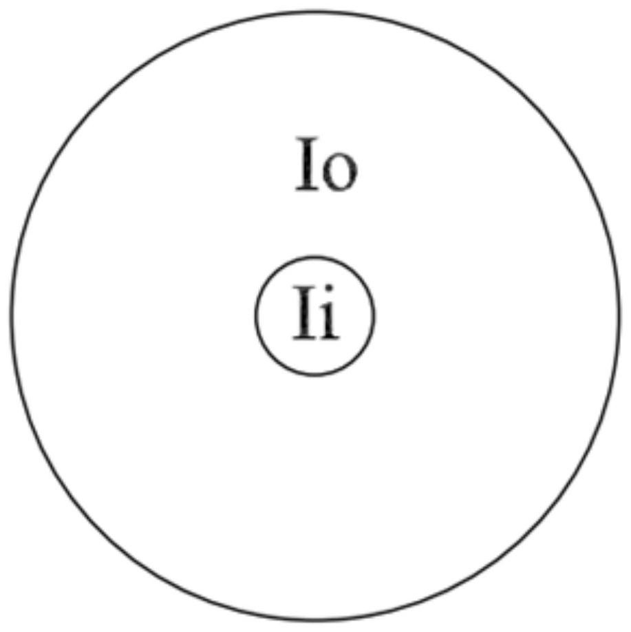
[0028] Step two and three: use the pixels on the CCD2 to calculate the evaluation function J k (u k ),in,

[0029] I i is the center of the CCD2 disc, I i the diameter is λ is the wavelength of the beacon light, λ is 808nm, f is the focal length of the CCD2 front lens, f is 20mm, D is the lens aperture, D is 10mm, I o Remove the disk center I in CCD2 i the ring, I o the diameter is J is the evaluation function, k represents the kth iteration result, and u represents the control voltage vector of the piezoelectric deformable mirror;

[0030] Step 24: Randomly generate a disturb...

specific Embodiment approach 3

[0036] Embodiment 3: This embodiment is a further description of Embodiment 2. The difference between this embodiment and Embodiment 2 is the change δJ of the evaluation function k Expressed as:

[0037]


PUM


Abstract

The invention discloses a space optical communication miniaturized terminal static aberration correction method, relates to the technical field of communication terminals, and aims to solve the problems that in the prior art, under the conditions of common optical path and poor initial aberration of a beacon light receiving optical path, the light spot quality of beacon light received by a CCD is poor, and the tracking function is not facilitated. According to the application, the condition that the initial aberration of the common light path and the beacon light receiving light path is relatively poor can be solved, the static aberration of the common light path and the beacon light receiving light path can be effectively eliminated by controlling the deformable mirror to generate a specific initial compensation surface type, the light spot quality of the beacon light received by the CCD can be improved, and the implementation of tracking is facilitated.

Description

technical field [0001] The invention relates to the technical field of communication terminals, in particular to a static aberration correction method for a miniaturized terminal of spatial optical communication. Background technique [0002] In the space optical communication terminal where receiving and transmitting are in the same optical path, adaptive optics is used to correct the wavefront aberration of transmitting and receiving signals and beacon light. At this time, the communication terminal has one common optical path and five non-common optical paths. Among them, the wavefront detection optical path only plays the role of detecting wavefront aberration, and can calibrate its own initial aberration, so the communication terminal requires its aberration is low, while the requirements for other non-common optical path aberrations are relatively high. However, the traditional adaptive optics system detects the wavefront aberration through the Shack-Hartmann wavefron...

Claims


Application Information

Patent Timeline
Patent Type & Authority Applications(China)
IPC IPC(8): G02B27/00G02B23/10
CPCY02D30/70
Inventor 于思源陈阳杨兴昊
Owner ZHEJIANG LAB
Why Eureka
Try Eureka