
Spectral imaging device based on adaptive optics

A technology of adaptive optics and spectral imaging, which is applied in astronomical spectral imaging and optical fields, can solve problems such as inability to apply rapid changes, achieve the effects of overcoming atmospheric dynamic interference, eliminating static aberrations, and automatically adapting to environmental changes

Active Publication Date: 2017-04-05
INST OF OPTICS & ELECTRONICS - CHINESE ACAD OF SCI
View PDF3 Cites 10 Cited by
  • Summary
  • Abstract
  • Description
  • Claims
  • Application Information

AI Technical Summary

Problems solved by technology

[0004] The technical problem to be solved by the present invention is: the traditional spectral imaging method generally obtains complete imaging-spectral three-dimensional information through time-sharing scanning, which is more seriously affected by atmospheric disturbances and cannot be applied to rapidly changing targets

Method used


Image

  • Spectral imaging device based on adaptive optics
  • Spectral imaging device based on adaptive optics
  • Spectral imaging device based on adaptive optics

Examples


Embodiment Construction

[0026] In order to make the object, technical solution and advantages of the present invention clearer, the implementation manners of the present invention will be further described in detail below in conjunction with the accompanying drawings.

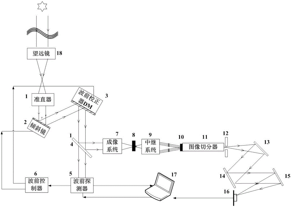
[0027] Such as figure 1 As shown, a spectral imaging device based on adaptive optics, the device includes a collimator 1, a tilting mirror 2, a wavefront corrector DM3, a dichroic beam splitter 4, a wavefront detector 5, and a wavefront controller 6 , imaging system 7, telescope primary image plane 8, relay optical system 9, telescope secondary image plane 10, image slicer 11, slit 12, collimating mirror 13, grating 14, imaging mirror 15, detector 16 and Data processing and control computer 17 is formed; Wherein:

[0028]After the telescope 18 images the astronomical target, it is collimated into parallel light by the collimator 1 and then enters the high-speed tilting mirror 2, which is used to correct the overall tilt of the wavefr...


PUM


Abstract

The present invention provides a spectral imaging device based on adaptive optics. The device comprises a collimator (1), a tilting mirror (2), a wavefront corrector DM (3), a dichroic spectroscope (4), a wavefront detector (5), a wavefront controller (6), an imaging system (7), a telescope instant image surface (8), a relay optical system (9), a telescope secondary image surface (10), an image splitter (11), a slit (12), a collimating lens (13), a grating (14), an imaging lens (15), a detector (16) and a data processing and control computer (17). The spectral imaging device based on the adaptive optics employs the dispersion light splitting mode after the image surface cutting conversion so as to obtain the object spectrum and image information while the single exposure; and moreover, through combination of the adaptive optics technology, the wavefront detector is introduced to detect the aberration in real time, and the tilting mirror and the wavefront corrector are configured to perform real-time correction so as to solve the problems of the atmospheric disturbance and the non-scanning rapid obtaining of the three-dimensional information and especially fit for the measurement of a rapidly changing target.

Description

technical field [0001] The invention relates to the field of optics, in particular to the technical field of astronomical spectral imaging, and proposes a spectral imaging device based on adaptive optics. Background technique [0002] Spectral imaging technology combines imaging technology and spectral technology. While obtaining the two-dimensional spatial feature imaging of the object, it also obtains the spectral information of the measured object, and can simultaneously obtain spatial and spectral information to generate a three-dimensional data cube. Its characteristic is that each image pixel can extract a spectral curve, and it is spatially identifiable. Due to the advantages of imaging and spectral measurement at the same time, it can not only complete the qualitative and quantitative analysis of spectral technology, but also perform morphological feature acquisition and spatial positioning. hotspot. [0003] Generally, a two-dimensional focal plane detector can on...

Claims


Application Information

Patent Timeline
IPC IPC(8): G01J3/02G01J3/28
CPCG01J3/0286G01J3/2823
Inventor 汤媛媛张雨东魏凯范真涛
Owner INST OF OPTICS & ELECTRONICS - CHINESE ACAD OF SCI
Learn More