Pulse frequency continuous abrupt change monitoring circuit

A monitoring circuit and pulse frequency technology, applied in the direction of electrical digital data processing, instruments, data processing input/output process, etc., can solve the problems of unfavorable system promotion and application, huge data, high cost and energy consumption, etc., to achieve Automatically adapt to environmental changes and judge the effect of accurate threshold

Pending Publication Date: 2022-03-01
浙江智识电子科技有限公司
View PDF1 Cites 0 Cited by
  • Summary
  • Abstract
  • Description
  • Claims
  • Application Information

AI Technical Summary

Problems solved by technology

This is because the slow change of the environment will lead to the drift of the output result (the value changes slowly), and the change brought by the environment change is different from the rapid change of the noise introduced by the interference. Therefore, a noise threshold needs to be set here, and noise judgment is required. , and the baseline update, and the judgment here is based on an absolute value, and then set the threshold, hysteresis range, baseline, noise threshold, etc. on the basis of the absolute value, so the data to be processed is huge and complex, so MCU + algorithm is required to cooperate with the processing In order to complete the final judgment, which in turn increases the system's demand for resources
In summary, this traditional capacitive sensing detection system not only has a complex circuit structure, but also requires AD conversion, and the conversion structure from capacitance to voltage (that is, C2V) is easily affected by external interference. The judgment process needs to be processed by MCU or filter, which eventually leads to The system has high complexity, large area, high cost and energy consumption, which is not conducive to the promotion and application of the system

Method used


Image

  • Pulse frequency continuous abrupt change monitoring circuit
  • Pulse frequency continuous abrupt change monitoring circuit
  • Pulse frequency continuous abrupt change monitoring circuit

Examples


Embodiment Construction

[0032] combine Figure 3 to Figure 10 , which describes a specific embodiment of the present invention in detail, but does not limit the claims of the present invention in any way.

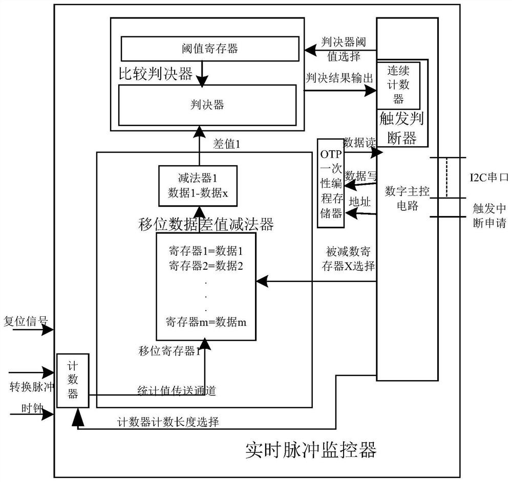
[0033] Such as image 3 As shown, a pulse frequency continuous mutation monitoring circuit includes a counter, a shift data difference subtractor, a comparison judge, a one-time programming memory and a digital master control circuit;

[0034] The external circuit provides a reset signal for the pulse frequency continuous mutation monitoring circuit, provides a clock for the counter, and the counter receives the monitored pulse signal;

[0035] The counter counts the number of pulse signals received within the set reference clock number, and the statistical value is recorded as the converted pulse value and sent to the shift data difference subtractor;

[0036] The shift data difference subtractor stores the received conversion pulse value into the shift register, and subtracts the value with a ...


PUM


Abstract

The invention relates to the technical field of pulse circuits, in particular to a pulse frequency continuous abrupt change monitoring circuit which comprises a counter, a shift data difference subtractor, a comparison decision device, a one-time programmable memory and a digital main control circuit. The counter receives monitored pulse signals, counts the number of the pulse signals and sends a result to the shift data difference subtractor, the shift data difference subtractor stores the result into the shift register and carries out subtraction operation on the result and a certain subtrahend to generate a difference result, the comparison decision device receives the difference result and compares the difference result with a preset threshold value, and the comparison decision device sends the difference result to the shift register. And the digital main control circuit is responsible for controlling the operation of the whole circuit, receiving the judgment result, comparing the judgment result with a trigger condition, and outputting a trigger result to an upper computer. The circuit executes a threshold environment adaptive algorithm, the threshold does not drift, and when a system is delivered to a client, the client can directly use the circuit after simple OTP programming without re-development, so that the circuit is convenient to use.

Description

technical field [0001] The invention relates to the technical field of pulse circuits, in particular to a monitoring circuit for continuously changing pulse frequency. Background technique [0002] The principle of the existing capacitive sensing detection system is generally as follows: the circuit has an emitter TX and a receiving electrode RX, and the capacitor sub-capacitance or mutual capacitance is first converted into an electrical signal, and then through the ADC circuit, the voltage signal is digitized to obtain a specific The digital quantization value is judged by the judgment logic to give a conclusion based on the numerical quantization value. Such as figure 1 As shown, the invention patent of Chinese Patent Publication No. CN107247529A discloses a capacitive sensing detection scheme. It can be seen from the scheme that the capacitive sensing circuit has an emitter TX and a receiving pole RX. The capacitance is first converted into an electrical signal, and th...

Claims


Application Information

Patent Timeline
Patent Type & Authority Applications(China)
IPC IPC(8): G06F3/041G06F3/044
CPCG06F3/04166G06F3/044
Inventor 陈强俞超群郑杰中岳兆强
Owner 浙江智识电子科技有限公司
Why Eureka
Try Eureka