
Air cleaner, and engine control system

An air filter and filter technology, applied in engine control, machine/engine, electrical control, etc., can solve problems such as inability to measure air flow, achieve the effects of improving filtration efficiency, preventing aging, and improving accuracy

Active Publication Date: 2011-06-22
KOMATSU LTD
View PDF6 Cites 6 Cited by
  • Summary
  • Abstract
  • Description
  • Claims
  • Application Information

AI Technical Summary

Problems solved by technology

[0009] However, in this type of air filter, the air flow inside the housing is caused by the deviation of the filter paper of the outer cylinder filter itself and the positional relationship between the inner cylinder filter fixed inside the housing and the installed outer cylinder filter. Subtle changes, if the technology disclosed in the above-mentioned Patent Document 1 is simply used, there will be a problem that the air flow rate cannot be measured with high precision by the mass flow meter

Method used


Image

  • Air cleaner, and engine control system
  • Air cleaner, and engine control system
  • Air cleaner, and engine control system

Examples


Embodiment Construction

[0056] Embodiments of the present invention will be described below based on the drawings.

[0057] (Structure of the air filter 10)

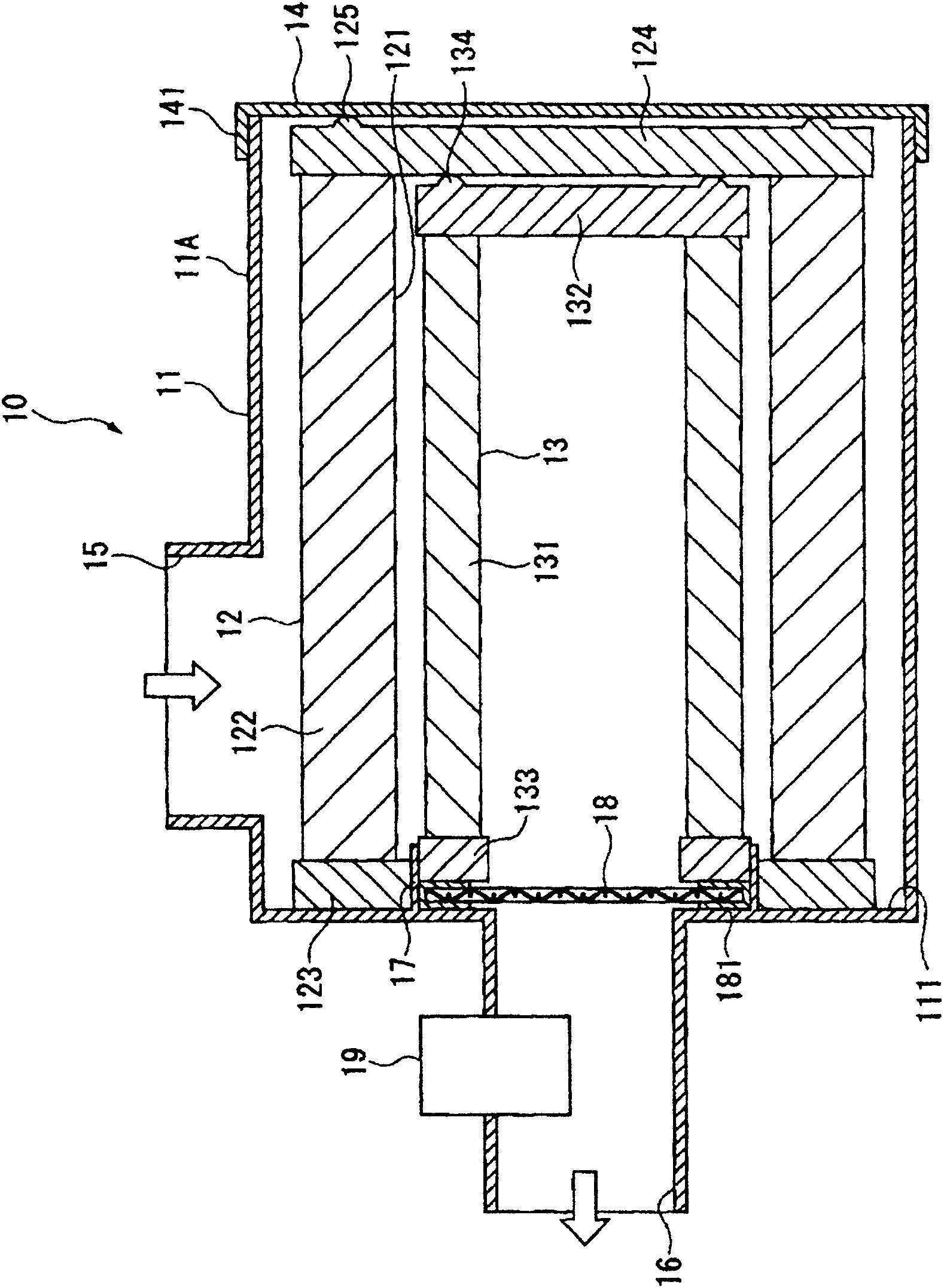
[0058] figure 1 It is a sectional view of the air filter 10 of this embodiment.

[0059] The air filter 10 is an airflow filtering device that takes in external air, removes dust from the air, and discharges it, and supplies the dust-free air to an engine or the like. The air filter 10 has a housing 11 , an outer cylinder filter 12 , an inner cylinder filter 13 , and a rectification grill 18 . The outer cylinder filter 12 and the inner cylinder filter 13 are concentrically arranged inside the casing 11 .

[0060] The case 11 accommodates the outer cylinder filter 12 and the inner cylinder filter 13 for filtering air, and has a case main body 11A and a cover member 14 closing an opening end surface of the case main body 11A.

[0061] The casing main body 11A is a bottomed cylindrical body made of synthetic resin or the like. The cover member...


PUM

PropertyMeasurementUnit
Wire diameteraaaaaaaaaa

Abstract

The invention relates to an air cleaner and an engine control system. The air cleaner (10) is provided with a housing (11) for housing therein an inner tube filter (13) and an outer tube filter (12) and comprising a case body (11A) having an open end face closed by a lid member (14). The housing (11) is provided with an air intake opening (15) provided in the outer peripheral surface of the case body (11A) and taking in outside air, and also with an air discharge opening (16) provided in a bottom surface (111) of the case body (11A), which bottom surface is located on the air flow downstream side of the case body, and discharging the air taken in from the air intake opening (15) and filtered by both the inner tube filter (13) and the outer tube filter (12). Inside the air discharge opening (16) is provided a mass flow rate sensor (19) for measuring the flow rate of the air. On the upstream of the mass flow rate sensor (19) is provided a flow regulating grid (18) for regulating the flow of the air.

Description

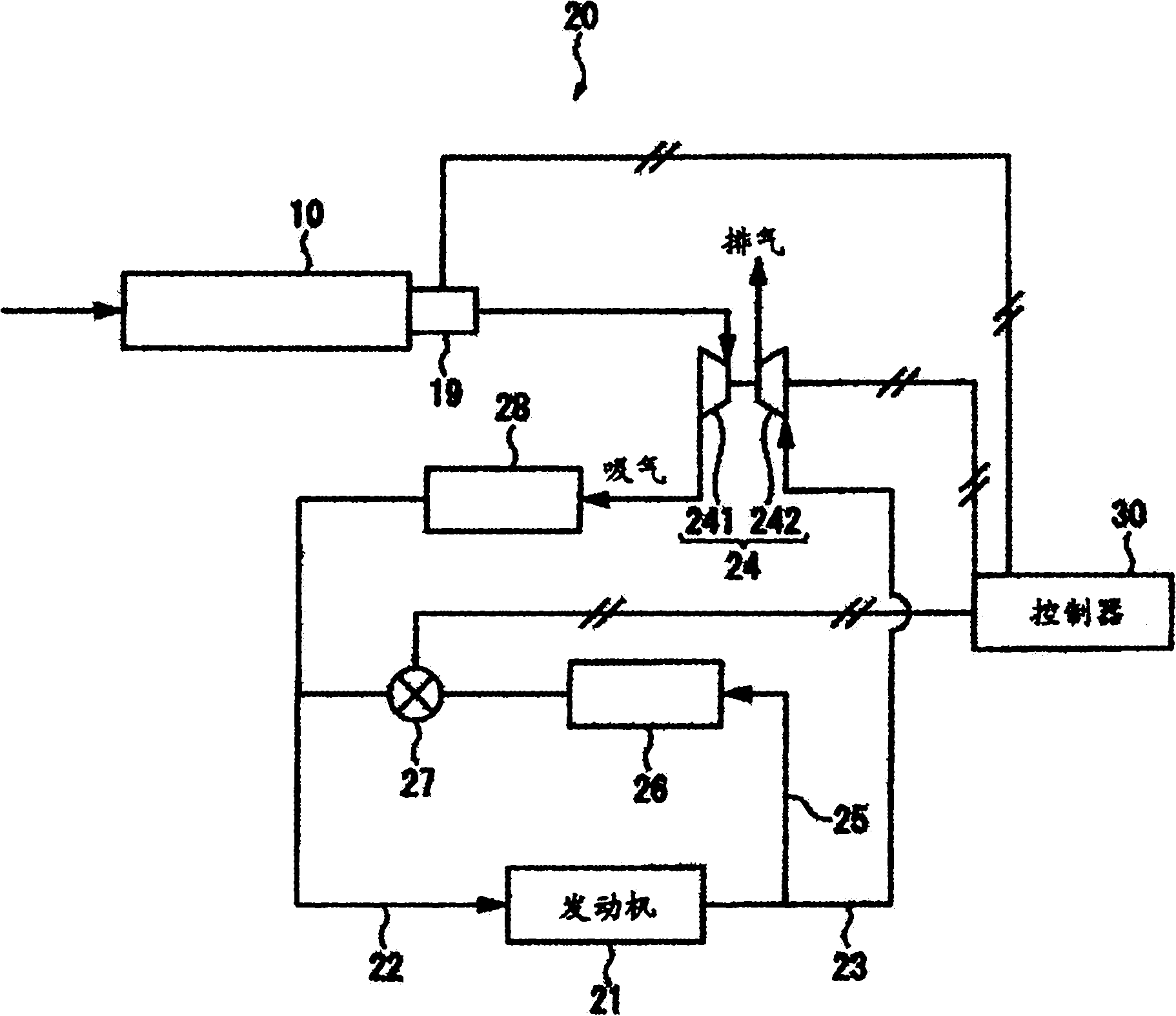
technical field [0001] The present invention relates to an air filter and an engine control system, and more particularly to an air filter and an engine control system that stabilize the flow rate of air supplied to an engine. Background technique [0002] Currently, there is known an exhaust gas recirculation device, the so-called Exhaust gas recirculation (EGR) system, which supplies a part of the exhaust gas discharged from the engine to the intake pipe to lower the combustion temperature of the diesel engine and suppress NO X generation. [0003] In addition, in such an EGR system, there is a system in which a variable turbocharger is provided on the downstream side of an air filter that sucks in outside air, and the air sucked in through the air filter is pressurized and supplied to the engine. Electronic control of opening of ERG valve or variable turbocharger nozzle. [0004] Among them, the mass flowmeter is used to measure the flow rate of the air filtered by the...

Claims


Application Information

Patent Timeline
IPC IPC(8): F02D35/00F02M35/024F02M35/10G01F1/00
CPCF02D41/0052F02M35/021F02M35/10262F02D41/0007F02M25/0707B01D46/444F02M25/0727F02D41/18B01D46/0024F02B29/0406F02M35/024B01D46/2411F02M25/0713F02M26/05F02M26/10F02M26/23B01D46/64F02D35/00F02M35/10F02M26/00F02D21/08G01F1/00
Inventor 并松宽仁岛津有宏饭岛正
Owner KOMATSU LTD
Learn More