A deadlock detection method for multi-robots in a control area
A deadlock detection and multi-robot technology, applied in the field of robotics, can solve problems such as scheduling failures and high computational complexity, and achieve the effect of avoiding deadlocks and maximizing system operating efficiency
- Summary
- Abstract
- Description
- Claims
- Application Information
AI Technical Summary
Problems solved by technology
Method used
Image
Examples
Embodiment 1
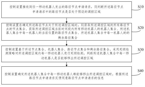
[0058] like figure 1 As shown in the figure, the embodiment of the present invention provides a deadlock detection method for multiple robots in a control area. The execution subject of the method in this embodiment may be the control device of all mobile robots in the control area. The following steps are corresponding to the second embodiment. The steps of deadlock detection; its specific implementation method includes the following steps:
[0059] S10. The control device receives a path node application request sent by any mobile robot, and determines whether the path node in the path node application request is in a preset control area; if so, execute step S20, otherwise, execute according to the existing method .
[0060] S20. When determining that the path node is in the control area, the control device obtains the node sets of all path nodes in the control area, obtains the robot sets of all mobile robots in the current time period of the control area, and the robot A...
Embodiment 2
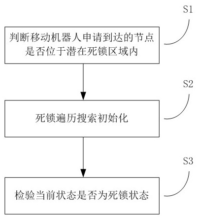
[0071] The method of this embodiment is to trigger the scheduling system to implement deadlock detection in the specified control area when any mobile robot applies to move to a certain path node in the specified control area. That is, when the scheduling system receives an application request for a path node in the control area from any mobile robot, it traverses the possible moving states of all mobile robots in the control area. For example, the traversal process can use depth-first search. If all mobile robots traversed to the control area can successfully leave the control area, it is determined that the control area is not deadlocked, and the scheduling system allows the mobile robots to occupy the requested path node to move; otherwise, if there is still movement until the end of the traversal If the robot cannot leave the control area, it is determined that the control area is in a deadlock state, and the scheduling system rejects the application request that the path n...
Embodiment 3
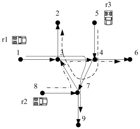
[0103] This embodiment combines image 3 The regulation method of a regulatory region shown is described in detail, image 3 A schematic diagram of a deadlock detection method for three mobile robots in the control area is shown.
[0104] like image 3 As shown, the scheduling system to which the three mobile robots belong has a total of 9 nodes. Located at node 1, it goes through the path nodes 1, 3, 4, 7, 9, to the destination node 9, located at node 8, which goes through the path nodes 8, 7, 3, 4, 6, to the destination node 6, Located at node 5, it goes to target node 2 through path nodes 5, 4, 7, 3, 2, and nodes 3, 4, and 7 in this network form a ring, which is a typical potential deadlock area. In the present embodiment, the method of the present embodiment is illustrated by a scheduling system running evolution process:
[0105] The first time to apply for a path node, the robot Apply for path node 3, step S1 determines that 3 belongs to the potential deadlock...
PUM
 Abstract
Description
Claims
Application Information
 - R&D
- Intellectual Property
- Life Sciences
- Materials
- Tech Scout
- Unparalleled Data Quality
- Higher Quality Content
- 60% Fewer Hallucinations
Browse by: Latest US Patents, China's latest patents, Technical Efficacy Thesaurus, Application Domain, Technology Topic, Popular Technical Reports.
© 2025 PatSnap. All rights reserved.Legal|Privacy policy|Modern Slavery Act Transparency Statement|Sitemap|About US| Contact US: help@patsnap.com


