Control technology used in distributed printing for printing control device and printer

a control technology and printing control technology, applied in the direction of digital output to print units, instruments, visual presentations, etc., can solve the problems of deadlock, stoppage of printing process, and interference of destination printers with the smooth execution of distributed printing, and achieve smooth distribution printing process

Inactive Publication Date: 2006-12-07
SEIKO EPSON CORP
View PDF10 Cites 30 Cited by
  • Summary
  • Abstract
  • Description
  • Claims
  • Application Information

AI Technical Summary

Benefits of technology

[0009] An advantage of some aspects of the invention is to provide a smooth distributed printing process.

Problems solved by technology

However, when the distribution method described above is used, there is the risk that the distribution destination printer may interfere with the smooth execution of the distributed printing.
In distributed printing wherein packet distribution is repeated to send the print job, there is the possibility that deadlock will occur wherein the distributed printing process will stop entirely (where deadlock will be described in detail below).
Thus, the printer may not make the device that sends the print jobs through the connections put into a waiting state.

Method used


Image

  • Control technology used in distributed printing for printing control device and printer
  • Control technology used in distributed printing for printing control device and printer
  • Control technology used in distributed printing for printing control device and printer

Examples


first embodiment

A.

[0046] Structure of a Distributed Printing System:

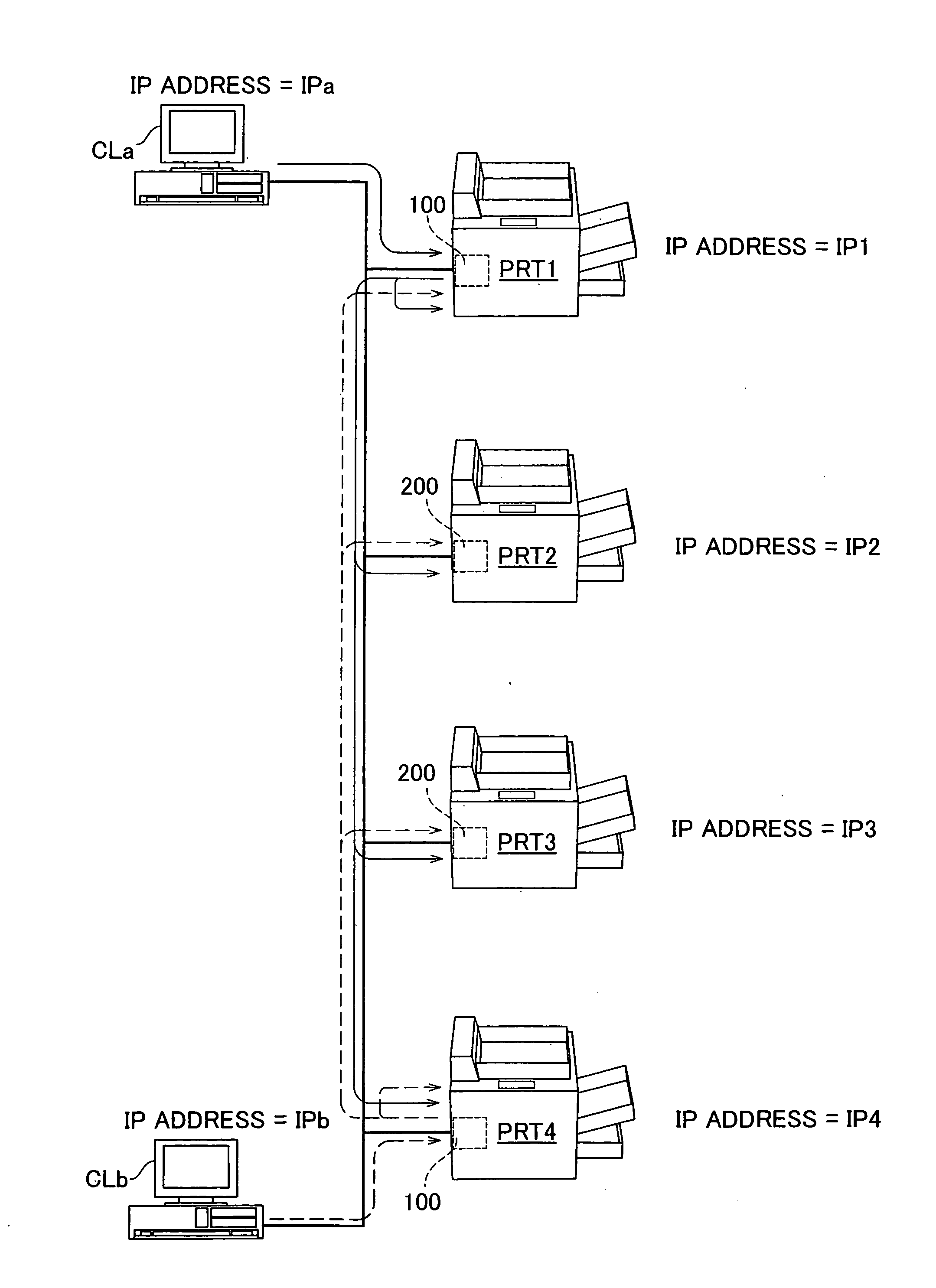
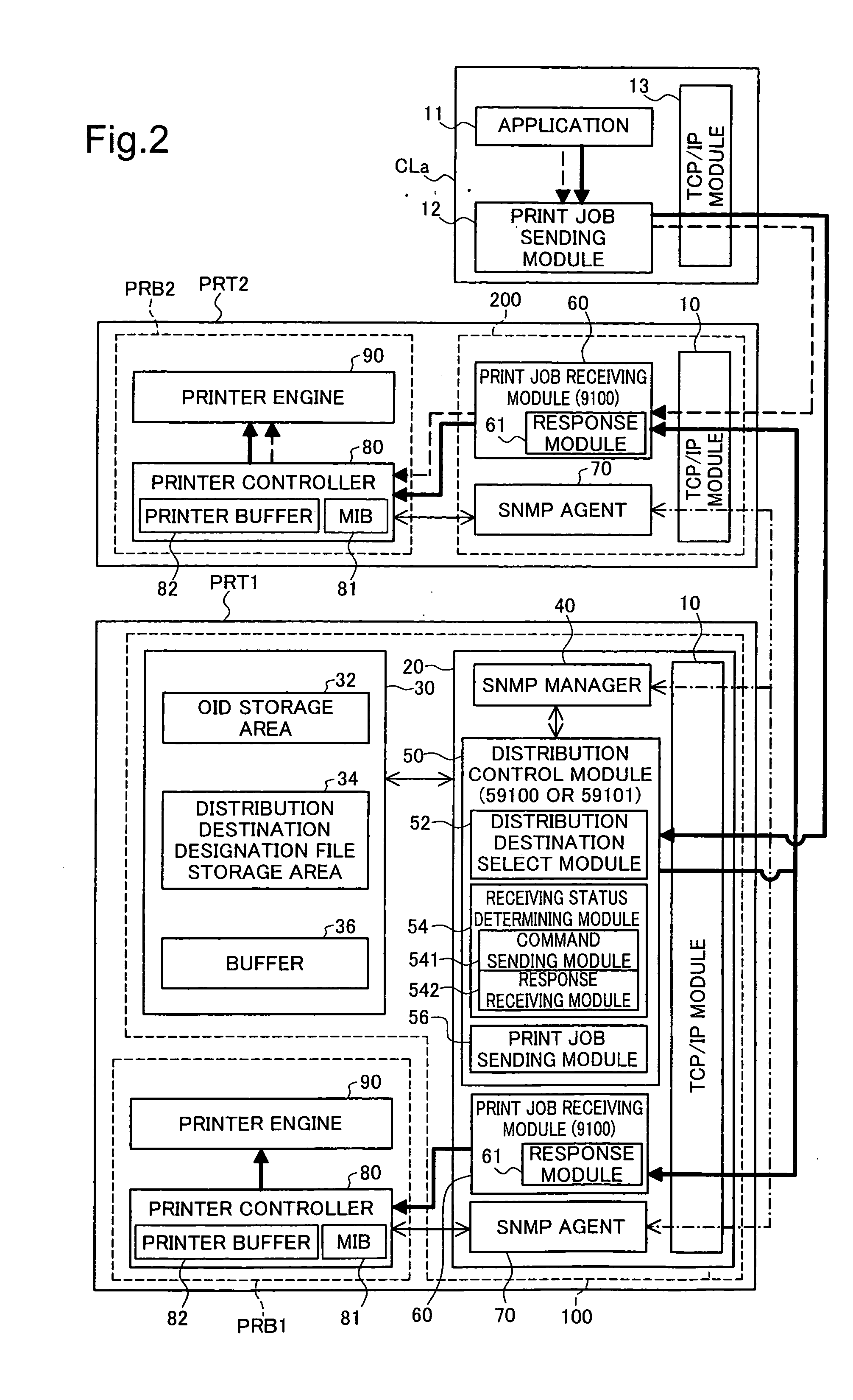
[0047] A configuration of a distributed printing system according to a first embodiment according to the present invention will be described referencing FIG. 1 and FIG. 2. FIG. 1 schematically shows a configuration of a distributed printing system according to a first embodiment. FIG. 2 shows a block diagram of the internal structure of each device in a distributed printing system according to the first embodiment.

[0048] This distributed printing system, as shown in FIG. 1, includes a plurality of computers as clients (hereinafter termed simply “client”) CLa and CLb, and a plurality of printers PRT1 through PRT4. The clients CLa and CLb are connected via a local area network (LAN) to printers PRT1 through PRT4. Communications between each of the devices is performed using the TCP-IP protocol, and this IP addresses are assigned to each of the devices. For convenience in explanation, it is here assumed that the IP addresses assigne...

second embodiment

B. Second embodiment

[0143] Structure of a Distributed Printing System

[0144] A configuration of a distributed printing system according to a second embodiment is the same as the configuration in the first embodiment, which was described in reference to FIG. 1, and thus the explanation thereof will be omitted. FIG. 13 shows a block diagram of the internal structures of each device in a distributed printing system according to a second embodiment.

[0145] When compared to the printer PRT1 in the first embodiment, the printer PRT1 in the second embodiment differs in that the configuration of the distribution control module 50 and the print job receiving module 60 within the custom network board 100. The distribution control module 50 in the second embodiment has an exclusive use request module 543 instead of the command sending module 541 in the first embodiment, and a notification receiving module 544 instead of the response receiving module 542. The exclusive use request module 543 se...

third embodiment

D. Third embodiment

[0191] Structure of the Distributed Printing System

[0192] A configuration of a distributed printing system according to a third embodiment will be described in reference to FIG. 21 and FIG. 22. FIG. 21 schematically shows the configuration of a distributed printing system according to a third embodiment. FIG. 22 shows a block diagram of the internal structure of each device that structures a distributed printing system according to the third embodiment.

[0193] The distributed printing system in the third embodiment, as shown in FIG. 21, includes separate printers PRTa1 through PRTa4, instead of printers PRT1 through PRT4 in the distributed printing system according to the first embodiment (FIG. 1). Other configuration for the distributed printing system in the third embodiment are the same as configuration in the distributed printing system in the first example embodiment, and so the same codes are assigned in FIG. 21 and FIG. 22 for components that are identical...


PUM


Abstract

To achieve a smooth distributed printing process, the printer includes a communication module, a job receiving module and a print executing module. The communication module maintains connections to perform communication using a connection-type protocol. The job receiving module receives print jobs through the connections. The number of the print jobs that can be received in parallel is M. The M is a natural number. The print executing module executes printing processes in parallel for the received print jobs. The number of connections that can be maintained simultaneously by the communication module is set to be less than the M.

Description

CROSS REFERENCE TO RELATED APPLICATIONS [0001] This application relates to and claims priority from Japanese Patent Applications No. 2005-163607, filed on Jun. 3, 2005 and No. 2005-180236, filed on Jun. 21, 2005, the entire disclosure of which is incorporated by reference. BACKGROUND [0002] 1. Technical Field [0003] The present invention relates to control technology used in distributed printing for printing control device and printer. [0004] 2. Description of the Related Art [0005] There are known distributed printing system wherein printing control devices that are connected to a plurality of printers distribute print jobs to the plurality of printers. In this technology it is possible to complete the printing of multiple copies in a short amount of time through allocating the number of copies to be printed to a plurality of printers and performing the printing in parallel. [0006] In this type of distributed printing system, there is a method wherein a print job is divided into a ...

Claims


Application Information

Patent Timeline
Patent Type & Authority Applications(United States)
IPC IPC(8): G06F3/12
CPCG06F3/1204G06F3/1213G06F3/1214G06K15/1859G06F3/1288G06K15/02G06F3/1261
Inventor SHIMA, TOSHIHIRO
Owner SEIKO EPSON CORP
Why Eureka
Try Eureka