
Fan impellor locking device and wind-driven power generator set

A technology for wind turbines and locking devices, applied in wind turbine components, wind turbine combinations, wind turbines, etc., can solve the problems of poor impeller locking operation repeatability, judgment error locking operation, lag, etc., and achieve high operation efficiency and accuracy. Fast and accurate operation, good operation repeatability

Active Publication Date: 2011-10-26
JIANGSU GOLDWIND SCI & TECH CO LTD
View PDF4 Cites 26 Cited by
  • Summary
  • Abstract
  • Description
  • Claims
  • Application Information

AI Technical Summary

Problems solved by technology

[0005] First of all, due to the uneven judgment experience and operational proficiency of the operators, there are problems such as the operator's judgment error on the impeller speed and the relative lag of the locking operation during the impeller locking process. There is no damage to the locking device caused by aligning the locking hole; at the same time, the impact of the locking pin will increase the impact load borne by the unit and affect the normal service life of the equipment
[0006] In addition, even if the operator has rich operating experience, there is still no guarantee that each impeller locking operation can be completed accurately; that is to say, manual impeller locking operation has poor repeatability and low efficiency
[0007] In addition, since the reasonable depth of the locking pin inserted into the locking hole cannot be known during the manual locking operation, and the joint surface of the locking pin and the locking hole is mostly set as a conical self-locking mating surface, it is often encountered due to operational errors. The problem of locking the locking pin caused by excessive fit between the locking pin and the locking hole, and once the locking pin is locked, it will cause a lot of inconvenience to equipment maintenance

Method used


Image

  • Fan impellor locking device and wind-driven power generator set
  • Fan impellor locking device and wind-driven power generator set
  • Fan impellor locking device and wind-driven power generator set

Examples


Embodiment Construction

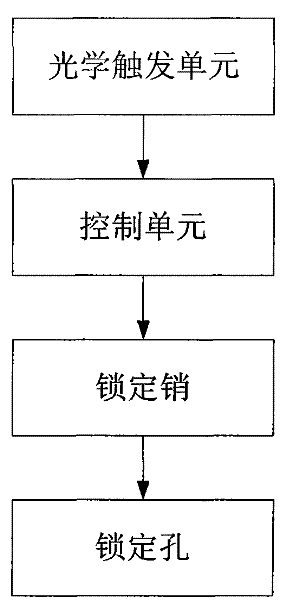
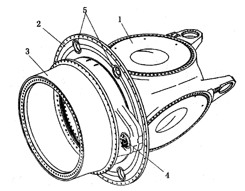
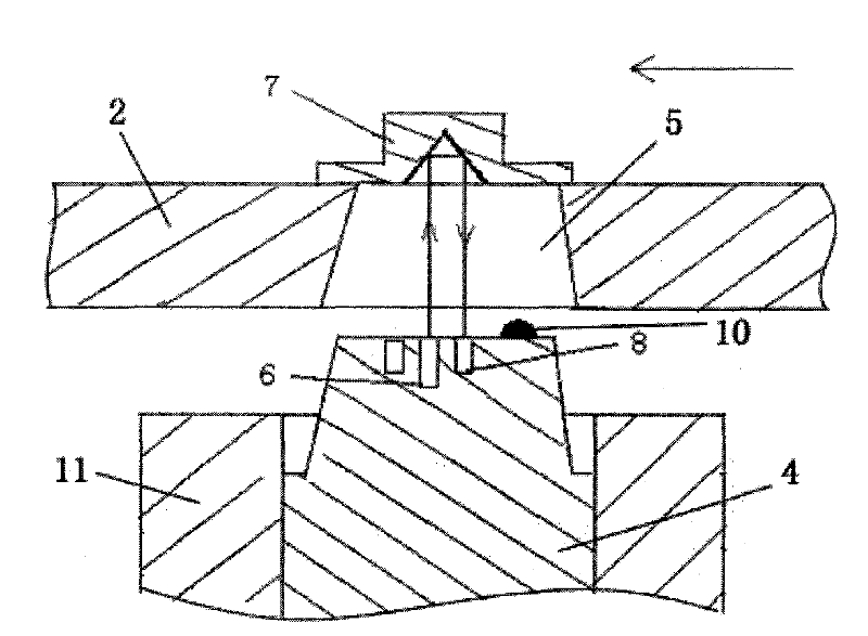
[0032] The fan impeller locking device provided by the present invention is mainly used for locking the impeller of the wind generating set, so that the staff can overhaul and maintain the wind generating set. Usually, the impeller is rotatably connected to the stator main shaft of the wind power generating set through the rotating shaft, and the fan impeller locking device provided by the present invention is arranged between the above-mentioned rotating shaft and the stator main shaft. The device specifically includes a locking pin arranged on the main shaft of the stator and a corresponding locking hole arranged on the rotating shaft, and an optical trigger unit and a control unit for controlling the locking pin to perform an automatic locking operation.

[0033] In order to enable those skilled in the art to better understand the technical solution of the present invention, the fan impeller locking device and the wind power generating set provided by the present invention w...


PUM


Abstract

The invention provides a fan impellor locking device which comprises a locking pin, a locking hole, an optical triggering unit and a control unit which are respectively arranged on a stator main shaft and a rotating shaft, wherein the optical triggering unit is used for sending triggering units to the control unit when the locking pin and the locking hole are aimed or to be aimed; and the control unit is used for driving the locking pin to execute corresponding locking motions according to triggering signals. The invention also provides a wind-driven power generator set with the fan impellor locking device. The automatic, efficient and accurate locking operations to the fan impellor can be realized through the fan impellor locking device and the wind-driven power generator set provided by the invention, and simultaneously the deadlock between the locking pin and the locking hole can be avoided effectively.

Description

technical field [0001] The invention relates to the technical field of wind power generation, in particular to a fan impeller locking device and a wind power generator set. Background technique [0002] In recent years, wind power generation technology has received extensive attention from governments of various countries, and thus has developed rapidly. During the installation, commissioning and daily maintenance of wind turbines, it is necessary to lock the impeller first to ensure the safety of operators and equipment. The above operations need to be realized by means of the impeller locking device installed on the unit. [0003] Currently, most of the impeller locking devices used require manual operation by operators based on experience and visual inspection results. Specifically, the impeller is first decelerated by blade pitch or mechanical friction brake. When the speed drops to a certain range, the operator judges and captures the locking position, and then manual...

Claims


Application Information

Patent Timeline
IPC IPC(8): F03D11/00F03D7/00F03D9/00
CPCY02E10/72
Inventor 李晓谦吴国庆程林志苏振年
Owner JIANGSU GOLDWIND SCI & TECH CO LTD
Learn More