
Jet oscillator

A technology of oscillators and jets, applied in showers, spray devices, spray devices, etc., can solve problems such as flooding and consumption

Pending Publication Date: 2022-04-12
AS AMERICA
View PDF0 Cites 0 Cited by
  • Summary
  • Abstract
  • Description
  • Claims
  • Application Information

AI Technical Summary

Problems solved by technology

To achieve the desired effect, use a large number of nozzles and consume a large amount of water

Method used


Image

  • Jet oscillator
  • Jet oscillator
  • Jet oscillator

Examples


example 1

[0052] Example 1 Shampoo Removal Test

[0053] In the following tests, the test wigs were treated with 25 mL of shampoo. The shampoo treated wigs were rinsed with water from a shower head comprising the multiple jet oscillators of the present invention (A) and commercially available shower heads (B) and (C). Rinse water samples were taken at 5 seconds and every 10 seconds thereafter. The rinse water samples were tested for turbidity, reported below in Nephelometric Turbidity Units (NTU). Lower NTUs correspond to cleaner samples. The distance from the shower head to the wig is about 190mm. The water flow rate was maintained at 1.45 gallons per minute. The water temperature is kept constant by a thermostatic valve and the hot and cold wires are independently pressure regulated to achieve the desired flow rate.

[0054]

[0055] The results show that the inventive showerhead (A) rinses the shampoo from the wig at a higher rate than the commercial showerheads (B) and (C), ...


PUM


Abstract

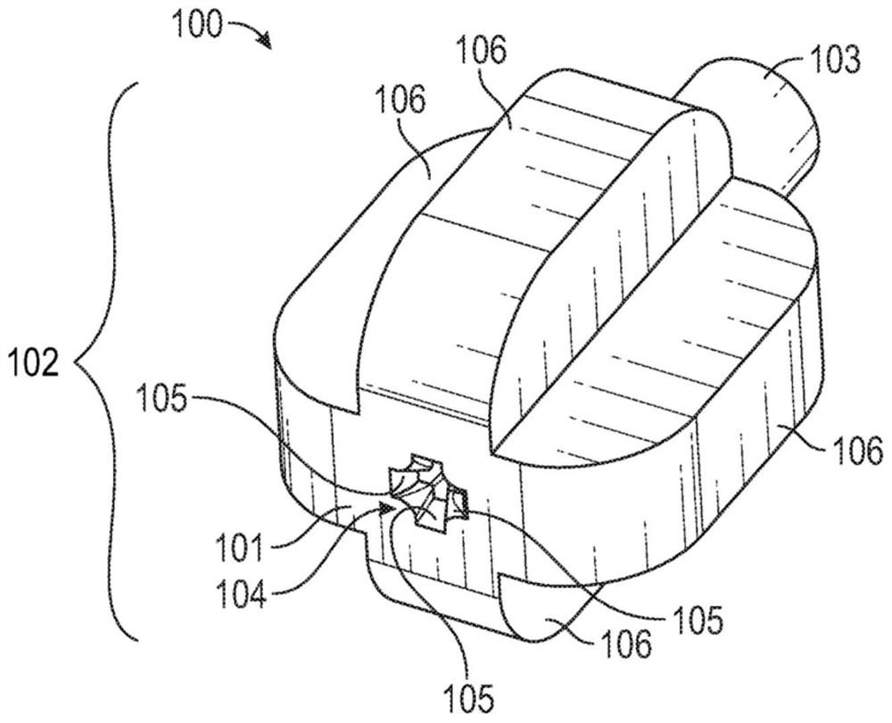
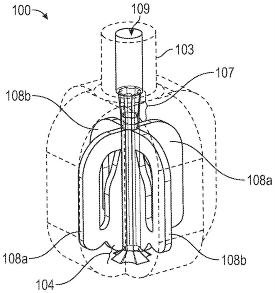
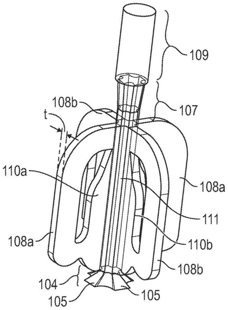
A fluidic oscillator includes an oscillator body including: an outer surface; an inner surface defining a three-dimensional space therein; a fluid inlet; and a fluid outlet, where the three-dimensional space, the fluid inlet, and the fluid outlet are in fluid communication, the three-dimensional space including a first fluid interaction region fluidly coupled to a first pair of feedback flow paths and a second fluid interaction region fluidly coupled to a second pair of feedback flow paths, and wherein the first fluid interaction region and the second fluid interaction region intersect.

Description

[0001] The present disclosure relates to a fluidic oscillator and a plumbing fixture including a fluidic oscillator. In some embodiments, the fluidic oscillator is a passive 3D oscillator. Background technique [0002] Shower heads typically include multiple small circular nozzles designed to moisten an area and provide a pleasant showering experience. To achieve the desired effect, a large number of nozzles are used and a large amount of water is consumed. [0003] There is a need for a water efficient shower head capable of delivering water to a designated area while providing a pleasant showering experience with the desired cleansing and rinsing benefits. Contents of the invention [0004] Accordingly, a fluidic oscillator is disclosed comprising an oscillator body comprising: an outer surface; an inner surface defining a three-dimensional space therein; a fluid inlet; and a fluid outlet, wherein the three-dimensional The space, the fluid inlet, and the fluid outlet are...

Claims


Application Information

Patent Timeline
IPC IPC(8): B05B1/02F15C1/16F15C1/22B05B1/08B05B1/16A47K3/28B05B1/30
CPCB05B1/08B05B1/18
Inventor N·S·科列加尔
Owner AS AMERICA
Learn More