Full coverage fluidic oscillator with automated cleaning system and method

a fluidic oscillator and automatic cleaning technology, applied in the direction of vehicle maintenance, vehicle cleaning, cleaning using liquids, etc., can solve the problems of increasing toxicological danger, further limited use, and raising toxicological concerns, so as to improve the spray performance of fluidic oscillators, improve the spray performance, and increase the downstream area

Inactive Publication Date: 2011-03-17
DLHBOWLES INC
View PDF0 Cites 52 Cited by
  • Summary
  • Abstract
  • Description
  • Claims
  • Application Information

AI Technical Summary

Benefits of technology

[0016]It is an object of the present invention to provide novel methods for increasing the downstream areas that can be wetted by the flows that are emitted by stationary spray nozzles.
[0017]It is also an objective of the present invention to improve upon the spray performance of fluidic oscillators.
[0018]Another object of the present invention to overcome the above mentioned difficulties by providing a convenient, inexpensive and unobtrusive automated system and method to clean, sanitize or disinfect structures or vessels having fluid-containing sidewalls such as toilet bowls, bidets and sinks.
[0019]Yet another object of the invention is to provide an easily installed, unobtrusive, inexpensive system adapted for safe, unattended operation to clean toilet bowls.

Problems solved by technology

Harsh chemicals have been employed in this cleaning task, and the results have often been noxious.
However, the presence of strong acids is known to be an irritant to the skin and further offers the potential of toxicological danger.
Generally, the compositions described in these patents are claimed to be effective in the removal of soap scum stains from such hard surfaces and may find further limited use in other classes of stains.
However, the formulations of most of the compositions within the aforementioned patents generally have relatively high amounts of acids (organic and / or inorganic) which raises toxicological concerns.
The prior art also includes automated deodorizing liquid dispensers (e.g., for use in urinals) or a variety of solid disk-shaped products intended to slowly dissolve in a toilet tank's water or in the bottom of a urinal, but those products do not offer adequate cleaning power and so provide an inadequate cleaning or disinfecting result.
All of these bowl cleaning methods have proven unsatisfactory, and so home-makers and custodians still clean toilet bowls by hand.

Method used


Image

  • Full coverage fluidic oscillator with automated cleaning system and method
  • Full coverage fluidic oscillator with automated cleaning system and method
  • Full coverage fluidic oscillator with automated cleaning system and method

Examples


Embodiment Construction

[0064]Before explaining exemplary embodiments and methods of the present invention in detail, it is to be understood that the invention is not limited in its application to the details of construction and to the arrangements of the components set forth in the following description or illustrated in the Figures. The invention is capable of other embodiments and of being practiced and carried out in various ways. Also, it is to be understood that the phraseology and terminology employed herein are for the purpose of description and should not be regarded as limiting.

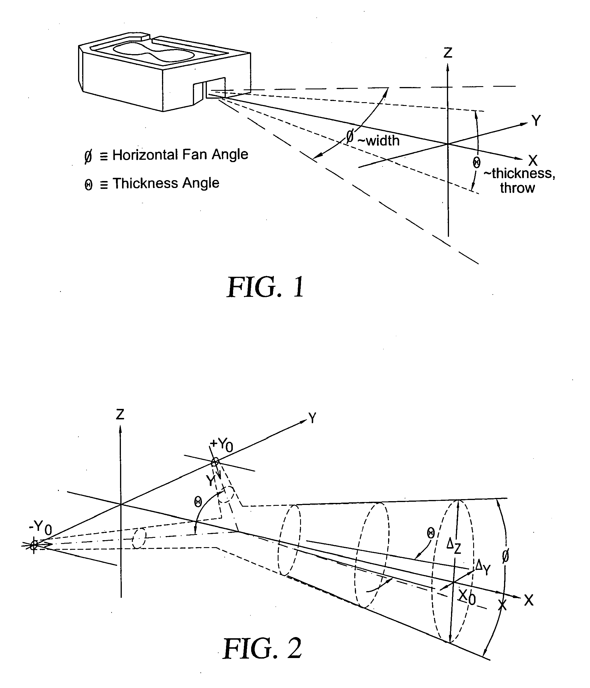
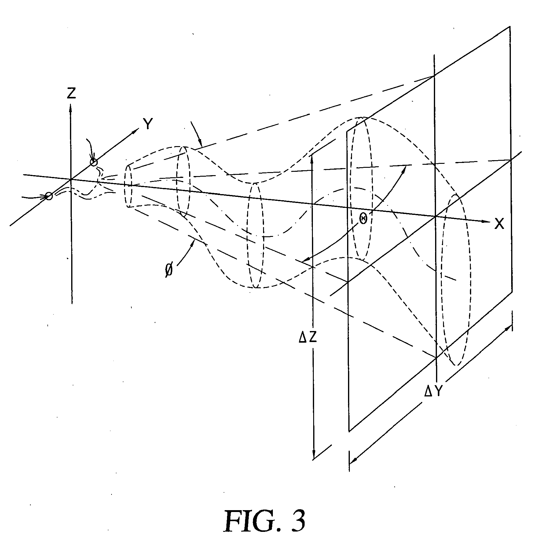
[0065]As noted above, FIG. 1 provides a frame of reference and spray from a fluidic oscillator spreads as it flows away from its origin at the oscillator's outlet. The centerline of the jet or spray is defined to be in the x-direction and it exhibits both a lateral-horizontal spread in the x-y plane (referred to as the “width” of the spray and due primarily to the unique flow phenomena occurring within the insert that yiel...


PUM


Abstract

A full coverage fluidic oscillator (2) includes a fluidic circuit member preferably having an oscillation inducing internal chamber, at least one inlet (8) or source of fluid under pressure, at least a pair of output nozzles (14, 16) connected to the source of fluid for projecting at least first and second impinging fluid jets into free space, where the first and second impinging jets collide or impinge upon one another at a selected jet angle to generate a substantially omni-directional sheet jet having selected thickness. The first and second jets are aimed at a pre-selected intersection point in free space where impingement is to occur. The sheet jet's thickness Δy is determined by the time-varying path or oscillation of each of the first and second impinging jets. The first and second impinging jets can be made to oscillate or pulsate by use of vortex generating amplifier structures (68, 70, 72, 149) within the internal chamber's fluid flow paths.

Description

PRIORITY CLAIMS AND REFERENCE TO RELATED APPLICATIONS[0001]This application claims priority to related, commonly owned U.S. provisional patent application No. 60 / 874,891, filed Dec. 14, 2006, the entire disclosure of which is incorporated herein by reference. This application also claims priority to related, commonly owned U.S. provisional patent application No. 60 / 960,261, filed Sep. 24, 2007, the entire disclosure of which is also incorporated herein by reference.BACKGROUND OF THE INVENTION[0002]1. Technical Field of the Invention[0003]This invention relates to new methods and apparatus for distributing the flow of liquid from a spray device and to methods and apparatus for automated cleaning or disinfecting for structures or vessels having fluid-containing sidewalls.[0004]2. Description of the Background Art[0005]Fluidic inserts or oscillators are well known for their ability to provide a wide range of distinctive liquid sprays. The distinctiveness of these sprays is due to the f...

Claims


Application Information

Patent Timeline
Patent Type & Authority Applications(United States)
IPC IPC(8): B08B9/00B05B7/04B05B17/04B05B1/08
CPCB05B1/08B08B5/02E03D2201/40E03D9/002B60S1/52
Inventor GOPALAN, SHRIDHARRUSSELL, GREGORY
Owner DLHBOWLES INC
Why Eureka
Try Eureka