Fixing device for external ventricular drainage

A fixing device and external drainage technology, applied in the field of medical devices, can solve the problems of pain, patient discomfort, bending and blocking of the drainage tube, etc., and achieve the effects of comfortable use, simple and convenient fixing, and not easy to tip over and move.

Pending Publication Date: 2022-04-15
THE SECOND AFFILIATED HOSPITAL OF SHANTOU UNIV MEDICAL COLLEGE
View PDF0 Cites 1 Cited by
  • Summary
  • Abstract
  • Description
  • Claims
  • Application Information

AI Technical Summary

Problems solved by technology

[0004] The present invention provides a fixing device for drainage outside the ventricle, which can effectively solve the problem that when the drainage fixing device proposed in the above-mentioned background technology is in use, the vibration and the displacement of the

Method used


Image

  • Fixing device for external ventricular drainage
  • Fixing device for external ventricular drainage
  • Fixing device for external ventricular drainage

Examples


Embodiment

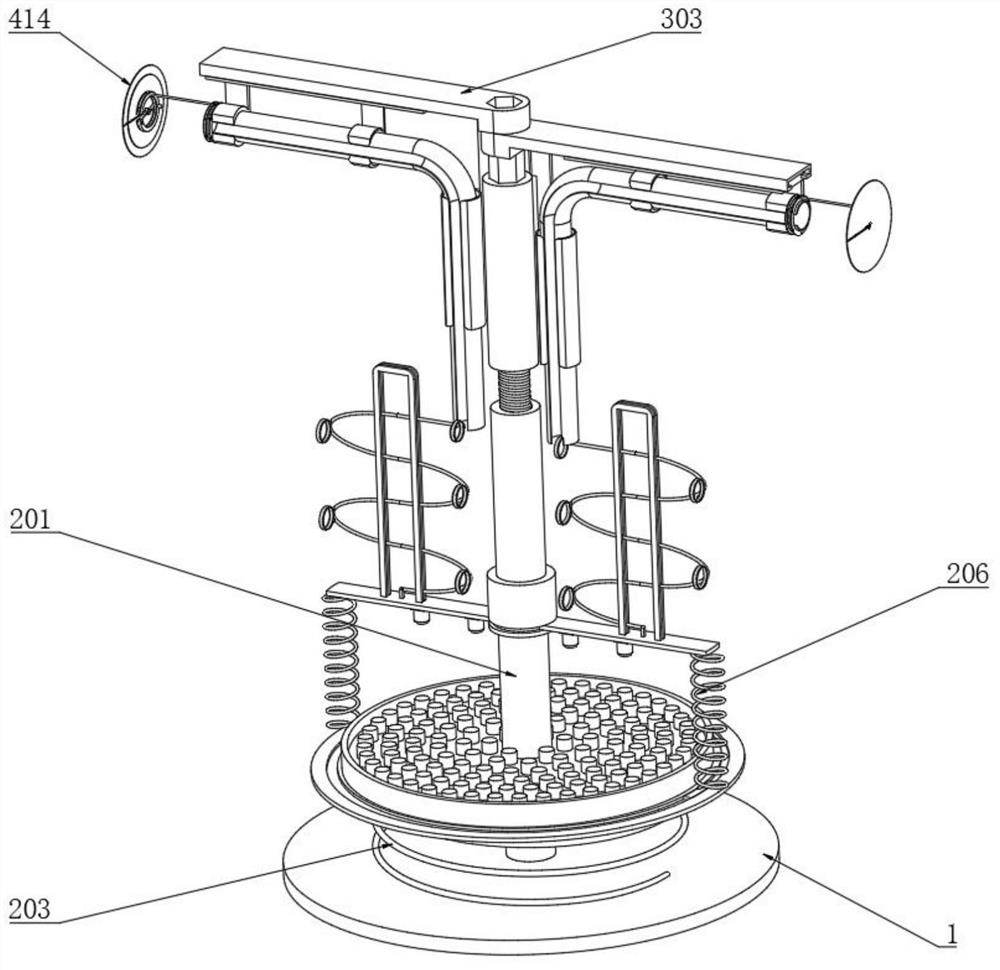
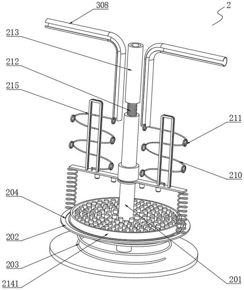
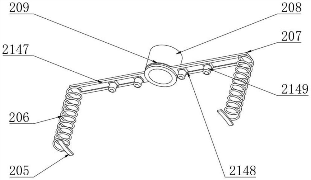
[0040] Example: such as Figure 1-2As shown, the present invention provides a technical solution for a fixing device for external ventricular drainage, including a bottom plate 1, a limit buffer assembly 2 is installed on the top surface of the bottom plate 1, and the limit buffer assembly 2 includes an internal thread support tube 201, a supporting plate 202, Bottom spring 203, annular top groove 204, arc slide block 205, side spring 206, rotating plate 207, sleeve pipe 208, annular bottom groove 209, S-shaped spring plate 210, threading ring 211, stud 212, ejector rod 213, Drainage bottle limiting assembly 214 and clamping frame 215;

[0041] The internally threaded support tube 201 is welded to the middle of the top surface of the base plate 1, and the bottom end of the internally threaded support tube 201 is movably sleeved with a support plate 202, and the support plate 202 and the base plate 1 are connected by a bottom spring 203, and the top edge of the support plate 20...


PUM


Abstract

A limiting buffer assembly is installed on the top face of a bottom plate, the bottom end of an internal thread supporting pipe is movably sleeved with a supporting plate, an edge spring is welded to the middle of the top face of an arc-shaped sliding block, an annular bottom groove is formed in the position, corresponding to the end of a rotating plate, of a sleeve, and threading rings are evenly welded to the middle of an S-shaped spring plate. A drainage bottle limiting assembly is arranged between the rotating plate and the supporting plate, the ejector rod is connected with a drainage tube protection assembly, and a disinfection anti-disengaging assembly is installed at one end of a protection tube. A drainage bottle is clamped and fixed through the rotating plate after being placed on the top face of the supporting plate, and the drainage tube is guided and limited through an S-shaped spring plate and a threading ring; the S-shaped spring plate deforms to be matched with the bending shape change when the drainage tube is pulled, the drainage tube is prevented from being bent and blocked, the supporting plate slides along the internal thread supporting tube for buffering, the influence of the fixing device on the position, connected with the human body, of the drainage tube is reduced, and therefore the device is more comfortable to use and better in safety.

Description

technical field [0001] The invention relates to the technical field of medical devices, in particular to a fixing device for external ventricular drainage. Background technique [0002] Continuous ventricle drainage is a medical operation, which is suitable for patients with severe intracranial pressure such as intraventricular or posterior fossa space-occupying lesions, frequent vomiting, physical weakness, and vision loss. Continuous ventricle drainage should be performed first, and then angiography and imaging should be performed after the condition improves. Surgery requires drainage for several days after the operation. The drainage fixture is a device used to fix the drainage device. Its function is to prevent the drainage device from toppling over and the pipeline to be entangled, and to assist drainage. [0003] However, when the current drainage fixture is used, the vibration and the displacement of the fixture will pull the drainage tube to move, which will easily ...

Claims


Application Information

Patent Timeline
IPC IPC(8): A61M1/00
Inventor 林佩珠肖子彤张敏鸿
Owner THE SECOND AFFILIATED HOSPITAL OF SHANTOU UNIV MEDICAL COLLEGE
Why Eureka
Try Eureka