Test tube cleaning equipment for biological experiment

A technology for cleaning equipment and biological experiments, which is applied in the field of test tube cleaning equipment for biological experiments, and can solve problems such as time-consuming, labor-intensive cleaning, low cleaning efficiency, and cumbersome operation process

Pending Publication Date: 2022-04-15
林坚平
View PDF9 Cites 0 Cited by
  • Summary
  • Abstract
  • Description
  • Claims
  • Application Information

AI Technical Summary

Problems solved by technology

[0004] In order to overcome the fact that the test tubes used in the biological research and development process are generally cleaned manually, the cleaning efficiency is low, and the waste of water resources is large. After cleaning, the test tubes need to be dried in the drying equipment. Then the test tube is sterilized, the operation process of cleaning, drying and disinfection of the test tube is more complicated, and it needs to be operated separately, which is time-consuming and laborious, and has the disadvantages of low work efficiency. The purpose of the present invention is to provide automatic cleaning, automatic disinfection and quick drying. Test tube cleaning equipment for biological experiments

Method used


Image

  • Test tube cleaning equipment for biological experiment
  • Test tube cleaning equipment for biological experiment
  • Test tube cleaning equipment for biological experiment

Examples


Embodiment 1

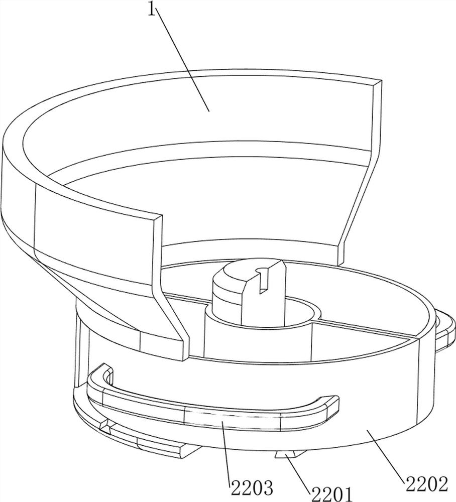
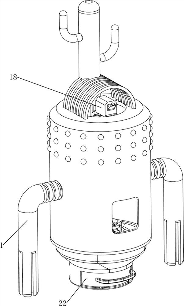
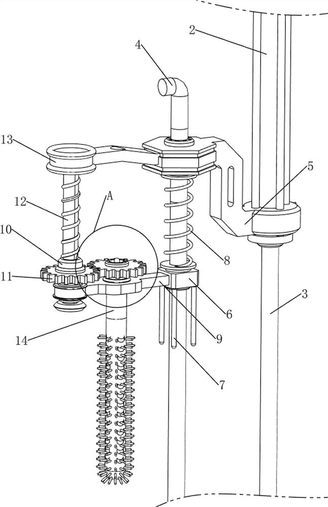
[0087] A test tube cleaning device for biological experiments, such as Figure 1-Figure 8 As shown, it includes a frame 1, a cylinder 2, an air rod 3, a first support rod 4, a first mounting block 5, a second mounting block 6, a touch lever 7, a first return spring 8, and a first mounting plate 9 , the first nut 10, the first spur gear set 11, the first screw rod 12, the mounting plate 13, the cleaning rod 14, the extruding rod 15, the second mounting plate 16, the drying mechanism 17 and the water discharge mechanism 18, the inner wall of the frame 1 The rear side of the upper part is equipped with a cylinder 2, the bottom of the cylinder 2 is provided with a first mounting block 5, and the middle of the lower part of the inner wall of the frame 1 is provided with a first support rod 4, and the first support rod 4 is connected with the top of the first mounting block 5. The telescopic rod is provided with an air rod 3, the first support rod 4 is slidably provided with a secon...

Embodiment 2

[0094] On the basis of Example 1, such as Figure 1-Figure 2 and Figure 8-Figure 13 As shown, it also includes a turning mechanism 19. The turning mechanism 19 includes a second mounting rod 1901, a third spur gear 1902, a third support rod 1903 and a first rack 1904. The front side of the second mounting plate 16 is rotatably provided with The second installation rod 1901, the front side of the second installation rod 1901 is provided with a third spur gear 1902, the front side of the lower part of the inner wall of the frame 1 is provided with a third support rod 1903, and the upper part of the third support rod 1903 is provided with a first rack 1904, The first rack gear 1904 cooperates with the third spur gear 1902 .

[0095] When the second mounting plate 16 moves upward, the upward movement of the second mounting plate 16 will cause the second mounting rod 1901 and the third spur gear 1902 to move upward, and the third spur gear 1902 will move upward to contact with the ...


PUM


Abstract

The invention relates to cleaning equipment, in particular to test tube cleaning equipment for biological experiments. The test tube cleaning equipment for the biological experiment has the advantages of automatic cleaning, automatic disinfection and quick wiping. Test tube cleaning equipment for biological experiments comprises a rack and an air cylinder, and the air cylinder is installed on the upper portion of the inner wall of the rack; the first mounting block is arranged at the lower part of the air cylinder; the first supporting rod is arranged in the middle of the lower portion of the inner wall of the rack, and the first supporting rod is connected with the upper portion of the first mounting block; the air rod is arranged on a telescopic rod of the air cylinder; the second mounting block is arranged on the first supporting rod in a sliding manner; and four touch rods are uniformly arranged at the bottom of the second mounting block. By arranging the cleaning rod and the water discharging mechanism, the extrusion rod moves upwards to enable water in the water discharging mechanism to fall into the cleaning rod, the cleaning rod rotates to clean the inner wall of the test tube, and automatic cleaning work of the test tube is achieved.

Description

technical field [0001] The invention relates to a cleaning device, in particular to a test tube cleaning device for biological experiments. Background technique [0002] Biological test tubes are widely used tools in the process of biological experiments. After the experiment is completed, impurities will remain in the test tubes. At this time, it is necessary to use a brush to clean the inside of the test tubes. However, in the prior art, in the process of biological research and development, The test tubes used are generally cleaned manually, the cleaning efficiency is low, and the waste of water resources is large. After cleaning, the test tubes need to be dried in a drying device. After drying, the test tubes are disinfected. The operation process of cleaning, drying, and disinfection is cumbersome and needs to be operated separately, which is time-consuming and laborious, and the work efficiency is low. [0003] For this reason, we propose a kind of test tube cleaning ...

Claims


Application Information

Patent Timeline
IPC IPC(8): B08B9/36B08B13/00B08B15/04F26B5/14A61L2/04
Inventor 林坚平
Owner 林坚平
Why Eureka
Try Eureka