Supporting device for testing engine performance and engine testing system

A technology of support device and engine, applied in the direction of engine test, measurement device, workpiece clamping device, etc., can solve the problems of easy height change, low precision, looseness, etc., to avoid height change, improve performance, and reliable operation. Effect

Pending Publication Date: 2022-04-15
李斯特测试设备(上海)有限公司
View PDF0 Cites 0 Cited by
  • Summary
  • Abstract
  • Description
  • Claims
  • Application Information

AI Technical Summary

Problems solved by technology

The Z-direction support method in the prior art is easy to change in height when it is locked after adjustment, resulting in low precision, or it is easy to cause loosening due to vibration during the test process when the clamping parts are locked.
The X and Y directions are adjusted by tapping with a hammer, which also has the problem of low adjustment accuracy.
If the position accuracy of the X, Y, and Z directions is not high, it is difficult to ensure that the engine crankshaft is coaxial with the drive shaft of the dynamometer, so that the stable and reliable operation of the engine test system cannot be guaranteed

Method used


Image

  • Supporting device for testing engine performance and engine testing system
  • Supporting device for testing engine performance and engine testing system
  • Supporting device for testing engine performance and engine testing system

Examples


Embodiment Construction

[0055] Embodiments of the present invention are described in detail below, and examples of the embodiments are shown in the drawings, wherein the same or similar reference numerals denote the same or similar elements or elements having the same or similar functions throughout. The embodiments described below by referring to the figures are exemplary and are intended to explain the present invention and should not be construed as limiting the present invention.

[0056] In the description of the present invention, it should be noted that the terms "center", "upper", "lower", "left", "right", "vertical", "horizontal", "inner", "outer" etc. The indicated orientation or positional relationship is based on the orientation or positional relationship shown in the drawings, and is only for the convenience of describing the present invention and simplifying the description, rather than indicating or implying that the referred device or element must have a specific orientation, or in a s...


PUM


Abstract

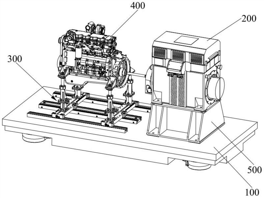
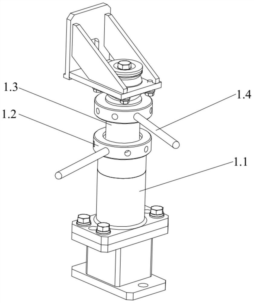
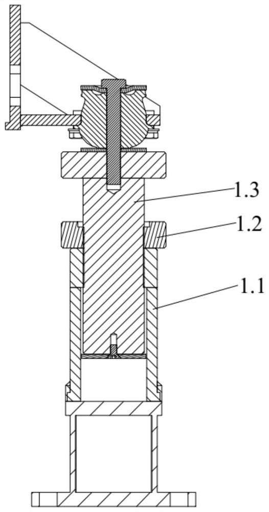
The invention discloses a supporting device for testing engine performance and an engine testing system, and relates to the field of engine testing. The engine supporting mechanism comprises a supporting sleeve, a first lead screw, a first lead screw nut and a locking nut, the first lead screw is arranged in the supporting sleeve, the first lead screw nut is in threaded fit with the first lead screw, the first lead screw nut is supported on the supporting sleeve, and the first lead screw can be driven to do linear motion by rotating the first lead screw nut; the lower portion of the locking nut is in threaded connection with the outer surface of the supporting sleeve, and the upper portion of the locking nut can press and fix the first lead screw nut and the first lead screw. A second lead screw nut is connected to the bottom of the supporting sleeve, a second lead screw is arranged on the first supporting piece, and the second lead screw nut can be driven by rotating the second lead screw to drive the supporting sleeve to be in sliding connection with the first supporting piece. The second supporting pieces are arranged at the two ends of the first supporting piece, the first supporting piece is driven by the gear and rack transmission mechanism to move relative to the second supporting pieces, and high-precision adjustment in the X direction, the Y direction and the Z direction is achieved.

Description

technical field [0001] The invention relates to the technical field of engine testing, in particular to a support device for testing engine performance and an engine testing system. Background technique [0002] In the field of engine testing, in order to test the performance of the engine, it is necessary to perform a performance test on the engine load under the conditions of simulating the actual working conditions of the engine (such as engine intake, engine exhaust, engine cooling system, etc.). The engine is loaded by applying a torque load to the engine through the drive shaft of the dynamometer. The support device for testing engine performance is used to support the engine during engine testing. [0003] At present, the commonly used engine support methods are basically similar: adjust the height with a screw in the Z direction, and lock it with bolts or nuts after adjustment; the position adjustment in the X and Y directions basically uses T-shaped nuts to slide a...

Claims


Application Information

Patent Timeline
Patent Type & Authority Applications(China)
IPC IPC(8): B25B11/00G01M15/02G01M15/00
CPCB25B11/00G01M15/02G01M15/00
Inventor 王树胜
Owner 李斯特测试设备(上海)有限公司
Why Eureka
Try Eureka