
Kneading machine

A kneader and chassis technology, applied in the field of mixing and mixing, can solve the problems of wasting materials, single screw feeding mode, and affecting the smooth progress of discharging work, so as to prevent materials from being thrown up and save materials.

Inactive Publication Date: 2022-04-15
南通协力方圆矿业设备有限公司
View PDF0 Cites 0 Cited by
  • Summary
  • Abstract
  • Description
  • Claims
  • Application Information

AI Technical Summary

Problems solved by technology

[0002] The kneader is an ideal equipment for kneading, kneading, vulcanization and polymerization of high-viscosity, elastic-plastic materials. According to the discharge method, the kneader is divided into hydraulic dumping, ball valve discharge and screw extrusion, etc., screw extrusion kneader The screw is fixedly connected to the outlet of the bottom surface of the hopper, and the outer wall of the screw is sleeved with a feeding sleeve, and the material is conveyed out through the screw and the stirring paddle of the kneader. The traditional screw and the feeding sleeve are directly fixed on the The outlet at the bottom of the hopper, the outer wall of the top of the feeding casing and the inside of the hopper are in a state of communication. When adding agitated materials into the hopper, some material particles will fall between the screw and the casing, which is located between the screw and the casing. The material stirring paddle between the sleeves cannot be stirred, which wastes a lot of material, and when the screw conveys the kneaded material, the material conveyed at the beginning will not be the stirred material, but the residue left between the screw and the screw when feeding. The material between the sleeves affects the smooth progress of the discharge work, and a large amount of material will be adhered to the outer wall of the screw after a long time of feeding. If these residual materials are not cleaned, it will directly affect the conveying efficiency of the finished material. In addition There is only one screw installed at the bottom of most screw extrusion kneaders, and the pitch of the screw is fixed. However, materials with high viscosity generally require a screw with a larger pitch to convey, which results in a single screw conveying. The material method is relatively simple

Method used


Image

  • Kneading machine
  • Kneading machine
  • Kneading machine

Examples


Embodiment Construction

[0033] The technical solutions in the embodiments of the present invention will be clearly and completely described below in conjunction with the embodiments of the present invention. Apparently, the described embodiments are only some of the embodiments of the present invention, not all of them. Based on the embodiments of the present invention, all other embodiments obtained by persons of ordinary skill in the art without creative efforts fall within the protection scope of the present invention.

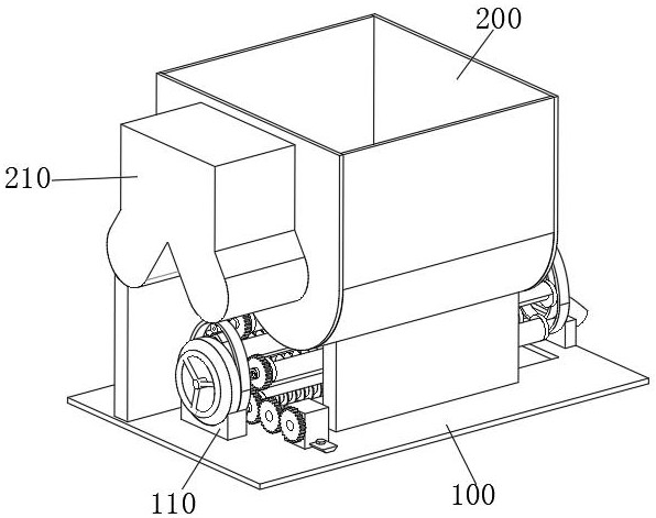
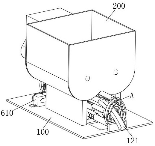
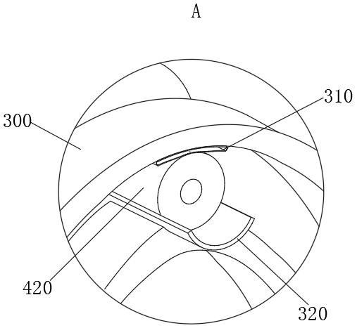
[0034] see Figure 1-11 As shown, a kneader includes a base plate 100, the two sides of the top surface of the base plate 100 are respectively fixedly connected with a support plate 1 and a support plate 2, the top surfaces of the support plate 1 and the support plate 2 are fixedly connected with a hopper 200, and one end of the hopper 200 The outer side of the base plate 100 is fixedly connected with a chassis 1 210 that drives the stirring paddle inside the hopper 200 to rotate,...


PUM


Abstract

The invention relates to the technical field of stirring and mixing, in particular to a kneading machine which comprises a base plate, a first supporting plate and a second supporting plate are fixedly connected to the two sides of the top face of the base plate respectively, a hopper is fixedly connected to the top face of the first supporting plate and the top face of the second supporting plate, and a first supporting seat and a second supporting seat are fixedly connected to the two ends of the top face of the base plate respectively. The top of the first supporting base and the top of the second supporting base are both fixedly connected with guide rails, and a plurality of material conveying modules are arranged between the two guide rails. According to the material conveying device, the transmission mechanism drives the material conveying modules close to the bottom face of the hopper to operate, material conveying can be achieved, the materials can be prevented from remaining in the material conveying modules, the material conveying speed is increased, the materials are saved, the second transmission mechanism drives the positions of the multiple material conveying modules to be switched, and the flexible and changeable material conveying modes are achieved; and conveying of the materials with different viscosities is met, the conveying module bonded with the materials is conveniently and automatically cleaned through the cleaning module, and cleanliness and tidiness of the conveying module are achieved.

Description

technical field [0001] The invention relates to the technical field of stirring and mixing, in particular to a kneader. Background technique [0002] The kneader is an ideal equipment for kneading, kneading, vulcanization and polymerization of high-viscosity, elastic-plastic materials. According to the discharge method, the kneader is divided into hydraulic dumping, ball valve discharge and screw extrusion, etc., screw extrusion kneader The screw is fixedly connected to the outlet of the bottom surface of the hopper, and the outer wall of the screw is sleeved with a feeding sleeve, and the material is conveyed out through the screw and the stirring paddle of the kneader. The traditional screw and the feeding sleeve are directly fixed on the The outlet at the bottom of the hopper, the outer wall of the top of the feeding casing and the inside of the hopper are in a state of communication. When adding agitated materials into the hopper, some material particles will fall betwee...

Claims


Application Information

Patent Timeline
Patent Type & Authority Applications(China)
IPC IPC(8): B29B7/24B29B7/26B29B7/80
Inventor 姜涛
Owner 南通协力方圆矿业设备有限公司
Learn More