Multi-angle positioning rotary table
A multi-angle, positioning and turning technology, applied in the direction of conveyor objects, transportation and packaging, etc., can solve the problems of not having multi-angle transportation, etc., to achieve the effect of easy hoisting and maintenance, convenient force transmission, and guaranteed stability
- Summary
- Abstract
- Description
- Claims
- Application Information
AI Technical Summary
Problems solved by technology
Method used
Image
Examples
Embodiment 1
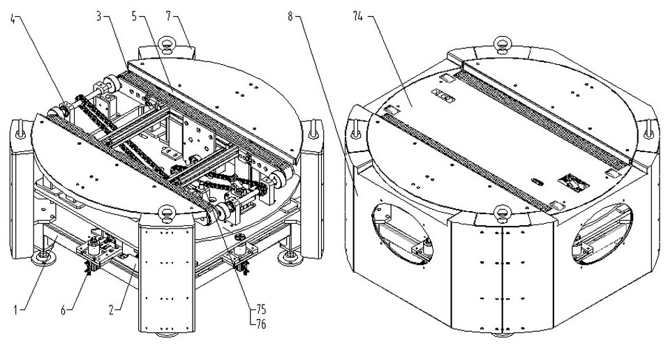
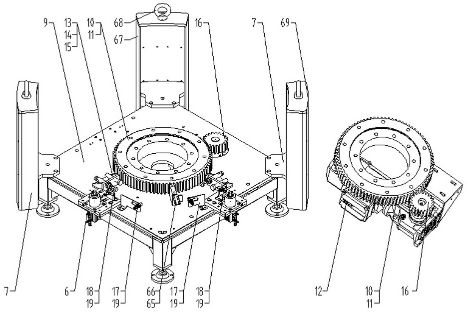
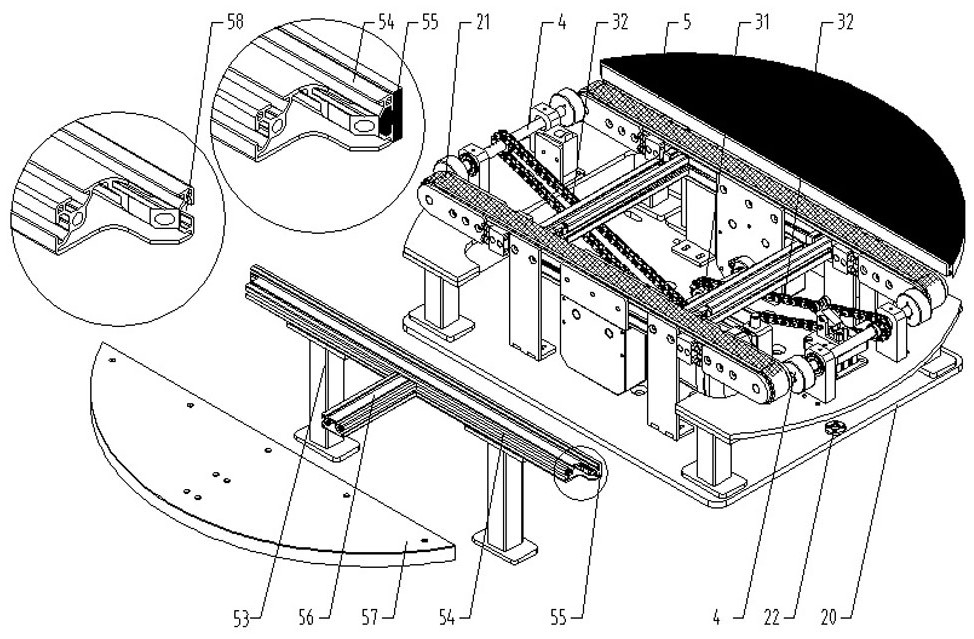
[0030] Example 1: See Figure 1-10, a multi-angle positioning turntable, including a frame 1, a rotary assembly 2 arranged on the frame 1. The synchronous belt conveyor assembly 3 arranged on the rotary assembly 2. The support roller assembly 4 that is arranged at the two ends of the slewing assembly 2 and the synchronous belt conveying assembly 3 . The guide assembly 5 arranged on both sides of the slewing assembly 2 and the synchronous belt conveying assembly 3 . The positioning cylinder assembly 6 arranged on the slewing assembly 2. Through the multi-angle rotation function of the slewing assembly 2, the synchronous conveying function of the synchronous belt conveying assembly 3, the guiding function of the guide assembly 5, the positioning function of the positioning cylinder assembly 6, the hoisting and maintenance function of the hoisting assembly 7 and the sealing plate assembly 8 Find faults and shut down for maintenance, cooperate with each other to realize multi-a...
Embodiment 2
[0054] Embodiment 2: The hoisting assembly 7 arranged around the slewing assembly 2 , the hoisting assembly 7 includes a hoisting plate 67 and a hoisting ring 68 .
[0055] The hanging plate 67 is fixed on the bottom plate 9, and the hanging plate 67 has a fan-shaped 69 structure.
[0056] The suspension ring 68 is fixed above the suspension plate 67 by screw connection.
[0057] Specifically, such as figure 1 and figure 2 As shown, when the transfer equipment needs to be transported, it is only necessary to lift the suspension steel cable through the suspension ring 68 upwards. The four corner suspension rings 68 ensure the stability of the overall suspension. The suspension plate 67 facilitates the transmission of force on the one hand. To ensure the stability of the machine body, on the other hand, the large surface area can protect the internal parts and realize the function of easy lifting and maintenance.
Embodiment 3
[0058] Embodiment 3: the sealing plate assembly 8 arranged around the rotary assembly 2 . The decorative panel 74 and the sealing plate assembly 8 arranged on the synchronous belt conveying assembly 3 include a viewing hole sealing plate 70 and a perspective plate 71 .
[0059] Both sides of the observation hole sealing plate 70 are circular arc-shaped mounting plates 80, which coincide with the arc surfaces of the hanging plate 67 and the sector 69.
[0060] The middle part of the sealing plate is a regular rectangular surface 72, and the regular rectangular surface 72 of the observation hole sealing plate 70 is provided with an elliptical observation window 73, and the periphery is provided with mounting holes for fixing the perspective plate 71.
[0061] A folded plate 77 with a guide groove is arranged above the observation hole sealing plate 70, and the periphery 79 of the folded plate in the direction of the rotation axis is an arc-shaped structure that matches the rotat...
PUM
 Abstract
Description
Claims
Application Information
 - R&D Engineer
- R&D Manager
- IP Professional
- Industry Leading Data Capabilities
- Powerful AI technology
- Patent DNA Extraction
Browse by: Latest US Patents, China's latest patents, Technical Efficacy Thesaurus, Application Domain, Technology Topic, Popular Technical Reports.
© 2024 PatSnap. All rights reserved.Legal|Privacy policy|Modern Slavery Act Transparency Statement|Sitemap|About US| Contact US: help@patsnap.com


