Reconstruction method based on existing septic tank, buffer tank and drainage system

A technology for septic tanks and water storage, which is applied in waterway systems, sewer pipe systems, sewage wells, etc., can solve the problems of high cost of combined pipe network renovation and environmental pollution, and achieve increased usable space, simple maintenance, and improved The effect of construction speed

Pending Publication Date: 2022-04-15
WUHAN SHENGYU DRAINING SYST
View PDF0 Cites 0 Cited by
  • Summary
  • Abstract
  • Description
  • Claims
  • Application Information

AI Technical Summary

Problems solved by technology

[0004] The technical problem to be solved by the present invention is that in rainy days, the sewage and rainwater are mixed and merged into the municipal confluence pipe together, causing environmental pollution or the technical defect of high cost of confluence pipe network transformation

Method used


Image

  • Reconstruction method based on existing septic tank, buffer tank and drainage system
  • Reconstruction method based on existing septic tank, buffer tank and drainage system
  • Reconstruction method based on existing septic tank, buffer tank and drainage system

Examples


Embodiment 1

[0041] The septic tank includes a tank body, a water inlet and a water outlet opened on the tank body, and a number of baffles arranged inside the tank body. The baffles are arranged at intervals from the water inlet to the water outlet. water hole. Since the water inlet and outlet of the septic tank in the prior art are respectively arranged on the opposite side walls of the tank body, and both are located above the side wall close to the top of the tank body, this structure causes the space in the septic tank to be basically filled. If the septic tank is full, the free space in the septic tank is insufficient, and the space in the septic tank cannot be used during the transformation of the combined pipe network. The small problem is that the space in the general community is limited, and there is not enough space to install a septic tank, so it is difficult to transform.

[0042] Based on this, this embodiment 1 provides a method based on existing septic tank transformation...

Embodiment 2

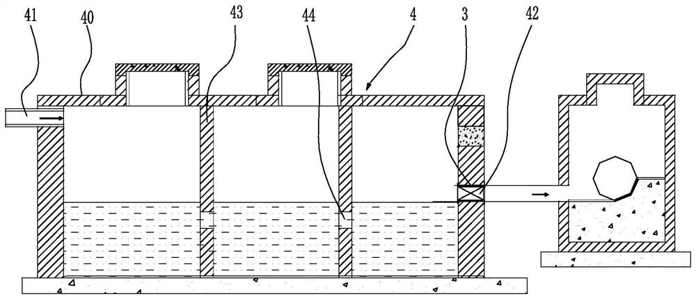
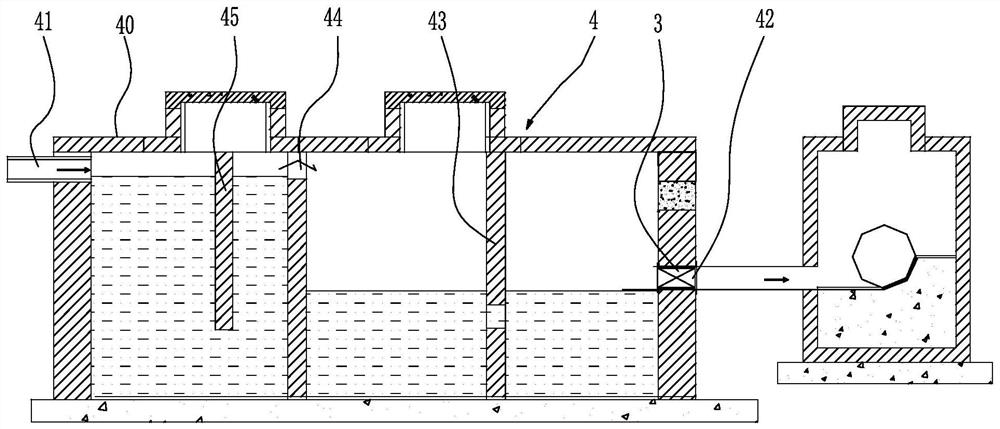
[0051] see Figure 2 to Figure 4 As shown, the second embodiment provides a slow filling tank based on the transformation of the existing septic tank. The slow filling tank 4 includes a tank body 40, a water inlet 41 and a water outlet 42 set on the tank body 40, and a Some baffles 43 inside the body 40, the baffles 43 are sequentially arranged at intervals from the water inlet 41 to the water outlet 42, the baffles 43 are provided with water holes 44, the water outlet 42 of the slow filling tank is connected to the sewage branch pipe 10, and The water outlet position of the water outlet 42 is lower than the water inlet position of the water inlet 41 , and the intercepting part 3 is arranged near the water outlet 42 . When the intercepting part 3 is closed, a part of the space in the slow filling tank 4 can be used to store domestic sewage, and the baffle plate 43 in the slow filling tank 4 can stop a part of garbage pollutants from flowing into the downstream pipeline, and th...

Embodiment 3

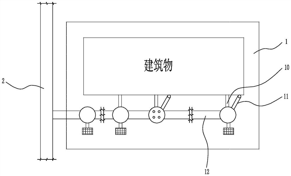
[0061] see Figure 5 As shown, the third embodiment provides a drainage system based on the transformation of existing septic tanks, including the slow filling tank 4 of the second embodiment above, the unit area 1 and the municipal confluence pipe 2; wherein, the unit area 1 includes at least one sewage The branch pipe 10, at least one rainwater outlet 11, the confluence branch pipe 12, the sewage branch pipe 10 is connected to the slow filling tank 4 and the confluence branch pipe 12, the rainwater outlet 11 is connected to the confluence branch pipe 12, and the end of the confluence branch pipe 12 is connected to the municipal confluence pipe 2, wherein, the sewage Both the branch pipe 10 and the rainwater outlet 11 are connected to the confluence branch pipe 12 , but there is no direct connection between the sewage branch pipe 10 and the rainwater outlet 11 .

[0062] In this embodiment, the specific structure of the slow charging pool 4 can be found in Embodiment 2, and w...


PUM


Abstract

The invention provides a transformation method based on an existing septic tank, a slow filling tank and a drainage system, and the transformation method is as follows: a new water outlet is formed, and the horizontal height of the new water outlet is lower than that of an original water outlet; a closure part is arranged close to the new water outlet or in the downstream pipeline, the closure part is closed, the pool body stores water, the closure part is opened, and the pool body conveys water. The slow filling pool comprises a pool body, a water inlet and a water outlet which are formed in the pool body, and a plurality of baffles arranged in the pool body, the baffles are sequentially arranged at intervals from the water inlet to the water outlet, water passing holes are formed in the baffles, the water outlet position of the water outlet is lower than the water inlet position of the water inlet, and a closure part is arranged at the position close to the water outlet. The municipal confluence pipe is not transformed, and the problems existing in a confluence system pipe network are solved from the source.

Description

technical field [0001] The invention belongs to the technical field of municipal drainage, and in particular relates to a method based on existing septic tank transformation, a buffer pool and a drainage system. Background technique [0002] see figure 1 As shown, it is a schematic diagram of the existing combined pipe network. The combined pipe network includes the municipal combined pipe and the unit area. The unit area is equipped with a combined branch pipe, at least one sewage branch pipe, and at least one rainwater outlet. Both the sewage branch pipe and the rainwater outlet are connected. Into the confluence branch pipe, on sunny days, the domestic sewage flowing out of the drainage riser flows into the confluence branch pipe through the sewage branch pipe and enters the municipal confluence pipe. . If all the rainwater and sewage are sent to the sewage treatment plant for treatment, the processing capacity of the sewage treatment plant is limited, and the concentra...

Claims


Application Information

Patent Timeline
Patent Type & Authority Applications(China)
IPC IPC(8): E03F11/00E03F3/02
Inventor 周超
Owner WUHAN SHENGYU DRAINING SYST
Why Eureka
Try Eureka