Fabricated shear wall unit
A shear wall and prefabricated technology, applied in the direction of walls, building components, buildings, etc., can solve the problems of difficult quality inspection, low installation efficiency, etc., to reduce the construction period, improve the structural bearing capacity, and the structural stress path is simple and clear Effect
- Summary
- Abstract
- Description
- Claims
- Application Information
AI Technical Summary
Problems solved by technology
Method used
Image

Examples
specific Embodiment approach 1
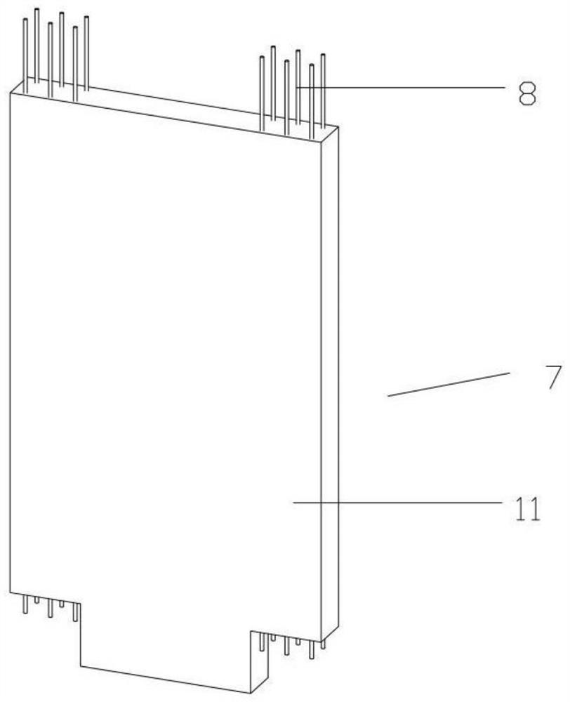
[0070] A prefabricated shear wall unit 7, characterized in that: the edge member 11 is provided with longitudinal bars 8 protruding from the concrete at the upper and lower ends, and the edge member 11 is provided with a gap to provide space for the installation of the connecting device 1, so that the longitudinal bars 8 can pass through the corresponding The mounting hole 5 that the upper connection plate 2 or the lower connection plate 3 of the connection device 1 is provided with is fixedly connected (as Figure 1-4 ).
[0071] Further, a gap is provided at the lower end of the edge member 11 of the prefabricated shear wall unit 7 to provide space for installing the connecting device 1 (such as Figure 1-4 ).
[0072] Further, the longitudinal bars 8 are only arranged in the range of the edge members 11, and the stirrups 14 are arranged around the longitudinal bars 8, and the tie bars 16 connect the horizontally distributed reinforcing bars 15 and the vertically distribute...
specific Embodiment approach 2
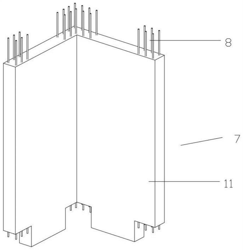
[0076] A prefabricated shear wall unit 7, characterized in that: the edge member 11 is provided with longitudinal bars 8 protruding from the concrete at the upper and lower ends, and the edge member 11 is provided with a gap to provide space for the installation of the connecting device 1, so that the longitudinal bars 8 can pass through the corresponding The mounting hole 5 that the upper connection plate 2 or the lower connection plate 3 of the connection device 1 is provided with is fixedly connected (as Figure 1-4 ).
[0077] Further, when installing the connection device 1 , the extension length of the ends of the longitudinal ribs 8 of the prefabricated shear wall unit 7 must meet the requirements of welding or connection with nuts 9 .
[0078] Further, the longitudinal reinforcement 8 of the prefabricated shear wall unit 7 is fixedly connected with the upper connection plate 2 or the lower connection plate 3 by welding or nuts 9 (such as Figure 24 ).
[0079] Furthe...
specific Embodiment approach 3
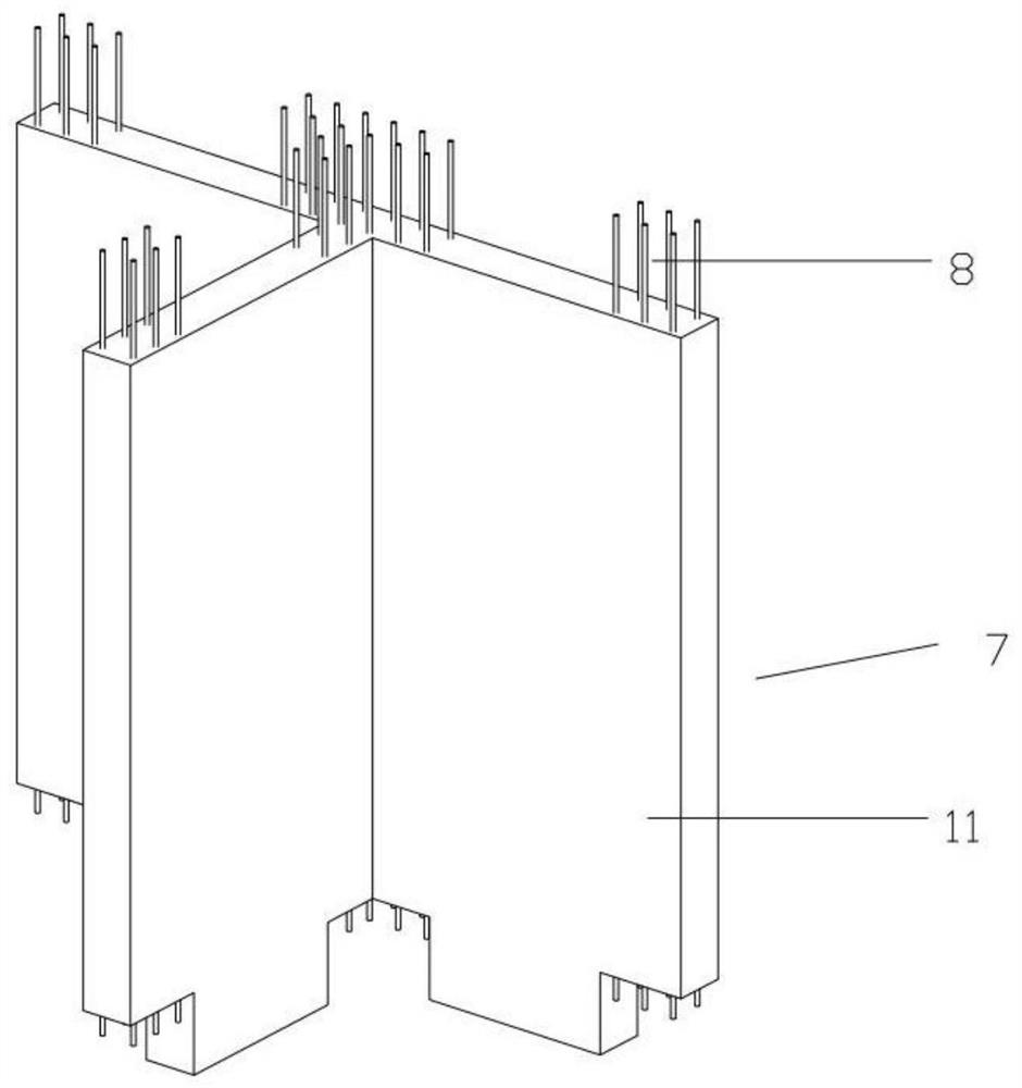
[0083] A prefabricated shear wall unit 7, characterized in that: the edge member 11 is provided with longitudinal bars 8 protruding from the concrete at the upper and lower ends, and the edge member 11 is provided with a gap to provide space for the installation of the connecting device 1, so that the longitudinal bars 8 can pass through the corresponding The mounting hole 5 that the upper connection plate 2 or the lower connection plate 3 of the connection device 1 is provided with is fixedly connected (as Figure 1-4 ).
[0084] Further, the connecting device 1 between the prefabricated shear wall units 7 includes an upper connecting plate 2, a lower connecting plate 3 and a short concrete-filled steel tube column 4, and the upper connecting plate 2 is provided with longitudinal The installation hole 5 through which the lower end of the tendon 8 can pass and be connected with it, the lower connecting plate 3 is provided with the installation hole 5 through which the upper en...
PUM
 Abstract
Description
Claims
Application Information
 - Generate Ideas
- Intellectual Property
- Life Sciences
- Materials
- Tech Scout
- Unparalleled Data Quality
- Higher Quality Content
- 60% Fewer Hallucinations
Browse by: Latest US Patents, China's latest patents, Technical Efficacy Thesaurus, Application Domain, Technology Topic, Popular Technical Reports.
© 2025 PatSnap. All rights reserved.Legal|Privacy policy|Modern Slavery Act Transparency Statement|Sitemap|About US| Contact US: help@patsnap.com