Expansion type tunnel device of high-speed railway tunnel portal and design method of expansion type tunnel device

A technology for high-speed railways and tunnels, applied in tunnels, mining equipment, earth-moving drilling, etc., can solve problems such as impact and unfavorable construction, and achieve the effect of reducing peak value, convenient implementation and simple structure

Active Publication Date: 2022-04-15
CHINA RAILWAY ERYUAN ENG GRP CO LTD
View PDF10 Cites 0 Cited by
  • Summary
  • Abstract
  • Description
  • Claims
  • Application Information

AI Technical Summary

Problems solved by technology

[0004] The purpose of the present invention is to provide a high-speed Enlarged Tunnel Device and Design Method for Railway Tunnel Entrance

Method used


Image

  • Expansion type tunnel device of high-speed railway tunnel portal and design method of expansion type tunnel device
  • Expansion type tunnel device of high-speed railway tunnel portal and design method of expansion type tunnel device
  • Expansion type tunnel device of high-speed railway tunnel portal and design method of expansion type tunnel device

Examples


Embodiment 1

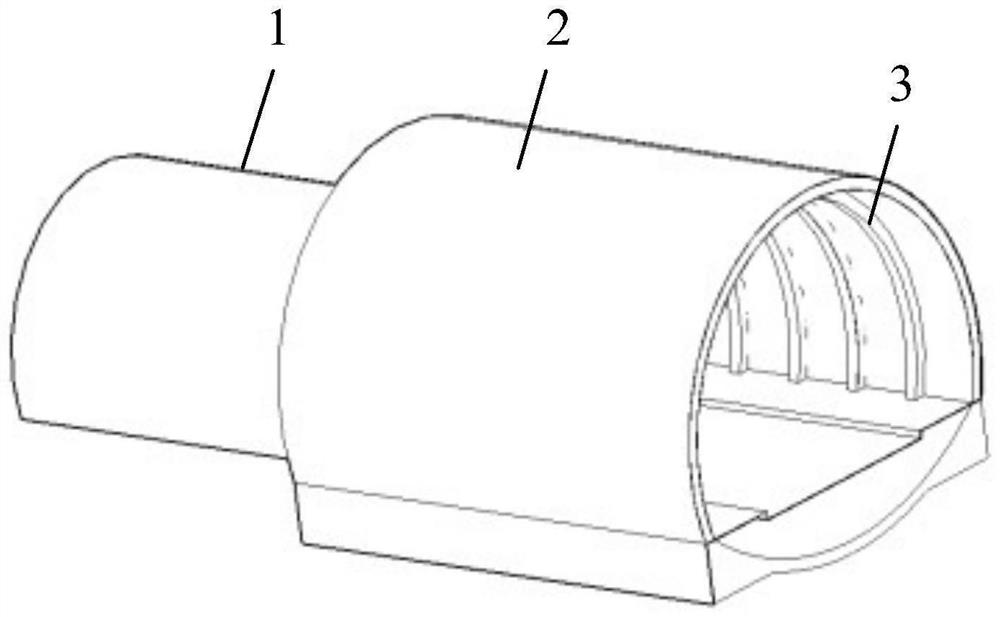
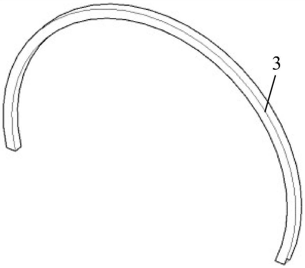
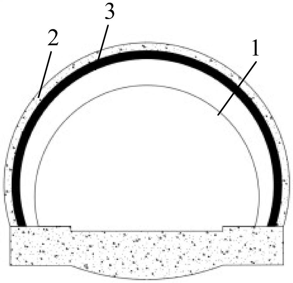
[0050] Such as Figure 1-7 As shown, the enlarged tunnel device of a high-speed railway tunnel entrance described in this embodiment includes an enlarged section tunnel 2 connected to the port of the standard section tunnel 1; the enlarged section tunnel 2 cross-sectional area Greater than the cross-sectional area of ​​the standard section tunnel 1, at least two rib-type sound-absorbing structures 3 are arranged on the inner wall of the enlarged-section tunnel 2, and the rib-type sound-absorbing structures 3 are arranged along the cross-section of the enlarged-section tunnel 2 , at least two of the rib-type sound-absorbing structures 3 are arranged at intervals along the axial direction of the enlarged cross-section tunnel 2, and all the rib-type sound-absorbing structures 3 divide the enlarged cross-section tunnel 2 into several first cavity segments in the axial direction 4. Each of the rib-type sound-absorbing structures 3 is surrounded by a second chamber section 5 .

[0...

Embodiment 2

[0069] Such as Figure 1-7 As shown, a kind of design method described in this embodiment is used for the enlarged tunnel device of a kind of high-speed railway tunnel entrance described in embodiment 1, specifically comprises the following steps:

[0070] Contains the following steps:

[0071] A1. Draw up the ratio between the cross-sectional clearance area of ​​the first cavity section 4 and the cross-sectional clearance area of ​​the second cavity section 5, and compare the ratio of the first cavity section 4 and the second cavity section 5 The cross-sectional clearance area ratio and the pressure gradient P of the pressure wave when the train just enters the enlarged cross-section tunnel 2 1 and pressure wave velocity v 1 input into the pressure wave decompression model, so that the pressure wave decompression model outputs the pressure P after the pressure wave passes through the enlarged section tunnel 2;

[0072] A2. The pressure wave step-down model outputs the pres...

Embodiment 3

[0099] Such as Figure 1-5 As shown, a design method described in this embodiment is used for the enlarged tunnel device of a high-speed railway tunnel entrance described in Embodiment 1, and is specifically illustrated by a test example: an enlarged tunnel device is set at the entrance and exit of the tunnel Tunnel 2 with large cross-section, the headroom area of ​​the tunnel with enlarged cross-section is 1.5 times that of the tunnel, and it is in the form of equal cross-section, with a length of 20m. The tunnel with enlarged cross-section is poured from ordinary C30 concrete;

[0100] Several rib-type sound-absorbing structures 3 are set inside the enlarged cross-section tunnel 2, which are poured from lightweight sound-absorbing concrete, and their cross-sections are rectangular or arc-shaped; the rib plates of the rib-type sound-absorbing structures 3 are parallel to the direction of the tunnel axis The width of the tunnel is 1m, and the cross-sectional area perpendicular...


PUM


Abstract

The invention relates to the technical field of tunnel engineering, in particular to an expanded tunnel device of a high-speed railway tunnel portal and a design method thereof, and the expanded tunnel device of the high-speed railway tunnel portal comprises an expanded section tunnel; the cross section area of the expanded section tunnel is larger than that of the tunnel, rib type noise reduction structures are arranged on the inner wall of the expanded section tunnel and arranged along the cross section of the tunnel, and at least two rib type noise reduction structures are arranged at intervals in the axial direction of the expanded section tunnel. The expanded section tunnel is divided into a plurality of first cavity sections in the axial direction through all the rib type noise reduction structures, and second cavity sections are defined by the rib type noise reduction structures. According to the expansion type tunnel device for the high-speed railway tunnel portal, when pressure waves pass through the expansion type section tunnel, the pressure waves can generate expansion and contraction effects in the area defined by the first cavity sections or the rib type noise reduction structures so as to reduce energy of the pressure waves, and therefore initial compression waves and micro-air-pressure waves of the tunnel portal are reduced.

Description

technical field [0001] The invention relates to the technical field of tunnel engineering, in particular to an enlarged tunnel device for a high-speed railway tunnel entrance and a design method thereof. Background technique [0002] With the rapid development of my country's transportation technology, the running speed of high-speed railway trains is also gradually increasing, and it has become possible for high-speed railways to run at a speed of 400km per hour. As vehicle speeds increase, tunnel aerodynamic issues become more pronounced. [0003] The problem of micro-pressure waves at the entrance of tunnels (that is, standard-section tunnels) has always been a hot topic in tunnel aerodynamics. Excessive micro-pressure waves will have a very adverse impact on the surrounding environment and buildings around the entrance. Studies have shown that the peak value of the micro-pressure wave at the tunnel entrance is proportional to the cube of the vehicle speed. When the trai...

Claims


Application Information

Patent Timeline
Patent Type & Authority Applications(China)
IPC IPC(8): E21D9/14
CPCE21D9/14Y02T90/00
Inventor 喻渝胖涛罗禄森杨伟超刘金松袁伟郑长青何昌国匡亮何洪龙游昊华阳王闯范雲鹤汪辉武
Owner CHINA RAILWAY ERYUAN ENG GRP CO LTD
Why Eureka
Try Eureka