High-power-density rack-mounted load

A high power density, rack-mounted technology, applied in the direction of instruments, electrical digital data processing, digital data processing components, etc., can solve the problems affecting the normal use of the load, high load surface temperature, small size and high power, etc., to achieve easy batch Production and assembly, large cooling power and small volume

Pending Publication Date: 2022-04-15
GUANGDONG FULLDE ELECTRONICS +2
View PDF0 Cites 0 Cited by
  • Summary
  • Abstract
  • Description
  • Claims
  • Application Information

AI Technical Summary

Problems solved by technology

[0003] With the development of electronic power technology, there are more and more requirements for the use of loads. Since the loads will generate more heat after being powered on, it is necessary to dissipate heat from the loads. When the loads are connected to the circuit to meet high power requirements When the resistance of the load increases, the heat generated on the load will increase greatly, which will easily make the temperature of the load surface too high and affect the normal use of the load.
The loads of the existing technology are difficult to meet the requirements of small size and high power at the same time

Method used


Image

  • High-power-density rack-mounted load
  • High-power-density rack-mounted load
  • High-power-density rack-mounted load

Examples


Embodiment Construction

[0024] The present invention will be described in detail below in conjunction with specific embodiments and accompanying drawings.

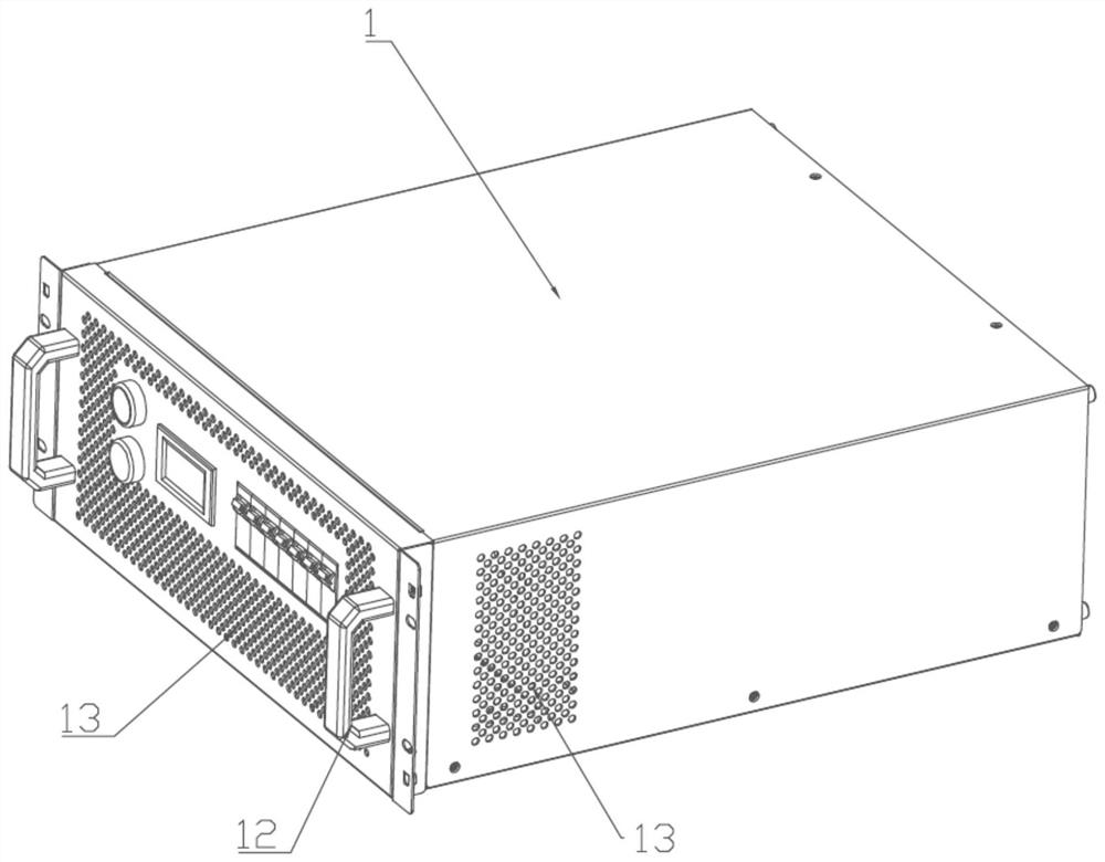
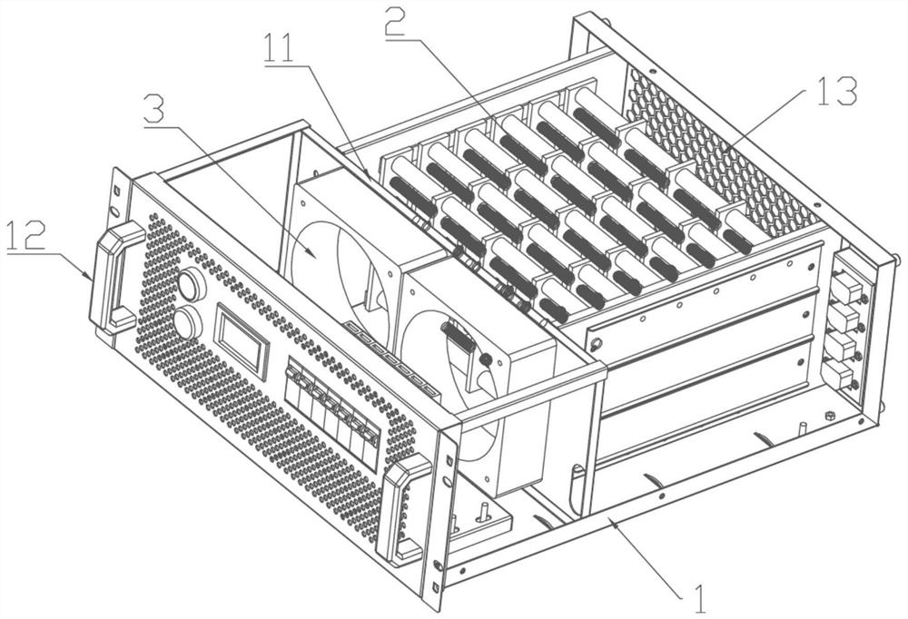
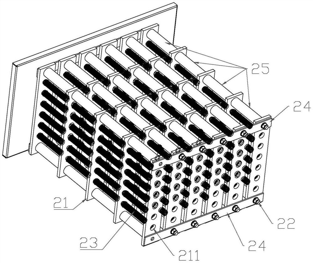
[0025] The high power density rack load of this embodiment, such as Figure 1 to Figure 3 As shown, it includes a box body 1 and a resistance unit 2 arranged in the box body 1, and the resistance unit 2 includes a plurality of parallel resistance rows, image 3 There are six resistor rows, each resistor row includes a plurality of insulating support plates 21, a locking assembly 22 and a plurality of spiral resistance strips 23, and the locking assembly 22 fixes and arranges the plurality of insulating support plates 21 at intervals . Each insulating support plate 21 has a plurality of support holes 211 along its length direction, image 3 Each insulating support plate 21 has six support holes 211, and a plurality of resistance strips 23 respectively pass through the support holes 211 aligned with the plurality of insulating support plates 21, ...


PUM


Abstract

The invention relates to the technical field of loads, in particular to a high-power-density rack-mounted load which comprises a box body and a resistor unit arranged in the box body, the resistor unit comprises a plurality of parallel resistor rows, and each resistor row comprises a plurality of insulating supporting plates, locking assemblies and a plurality of spiral resistor strips which are fixedly arranged at intervals. A plurality of supporting holes are formed in each insulating supporting plate in the length direction of the insulating supporting plate, a plurality of resistor strips penetrate through the supporting holes respectively, and the center line of each resistor strip is kept to be a straight line depending on the strength of the resistor strip; connecting plates are arranged among the plurality of resistor rows, so that the plurality of resistor rows are fixedly arranged at intervals; and the resistor strips of each resistor row are electrically connected with one another, and the resistor strips of the resistor rows are electrically connected with one another. The direct contact area of the spiral resistor strip and the air is large, the heat dissipation speed is high, and the heat dissipation power is large in unit volume. The overall load is small in size and large in power, and the power can be increased by two to three times under the same size compared with a conventional rack type load.

Description

technical field [0001] The invention relates to the technical field of loads, in particular to a rack-mounted load with high power density. Background technique [0002] Load resistors are also called discharge resistors, braking resistors, braking resistors or absorbing resistors due to their special functions. This type of resistor has high power and is generally a non-inductive power resistor. The non-inductive value and ultra-low inductive value are important for this type of product. requirements. [0003] With the development of electronic power technology, there are more and more requirements for the use of loads. Since the loads will generate more heat after being powered on, it is necessary to dissipate heat from the loads. When the loads are connected to the circuit to meet high power requirements When the resistance of the load increases, the heat generated on the load will increase greatly, which will easily make the temperature of the load surface too high and ...

Claims


Application Information

Patent Timeline
Patent Type & Authority Applications(China)
IPC IPC(8): G06F1/18G06F1/20
CPCG06F1/181G06F1/20
Inventor 陈俊丁羽刘霖陈乐
Owner GUANGDONG FULLDE ELECTRONICS
Why Eureka
Try Eureka