Cam welding machine

A welding machine and welding mechanism technology, applied in the direction of connection, line/collector parts, electrical components, etc., can solve the problems of large energy consumption, small application range, and poor structure, so as to reduce the power consumption of equipment and the application range Wide, labor-saving effect

Pending Publication Date: 2022-04-15
深圳市帆与航电子科技有限公司
View PDF0 Cites 0 Cited by
  • Summary
  • Abstract
  • Description
  • Claims
  • Application Information

AI Technical Summary

Problems solved by technology

[0002] With the continuous development of electronic technology, connectors, as a medium product for transmitting signals, are more and more widely used. Whether it is equipment for industrial production or mobile phones, computers, MP3s, etc. that people often use, connectors are used as a In the production process of the connector, the non-metallic outer layer of each branch body connection end of the wire is usually stripped and cut flat, and then matched with the connector for positioning and welding and fixing. However, the structure of the existing wire processing equipment is poor, and each process needs to be equipped with one or two powers to realize the stripping of the wire, the cutting operation and the feeding of the joint, the welding operation of the push and welding head, and the energy consumption Large, high cost, small scope of application

Method used


Image

  • Cam welding machine
  • Cam welding machine
  • Cam welding machine

Examples


Embodiment Construction

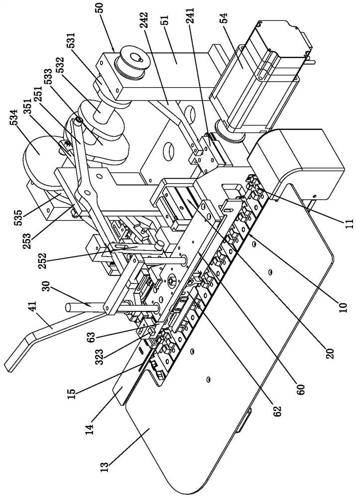
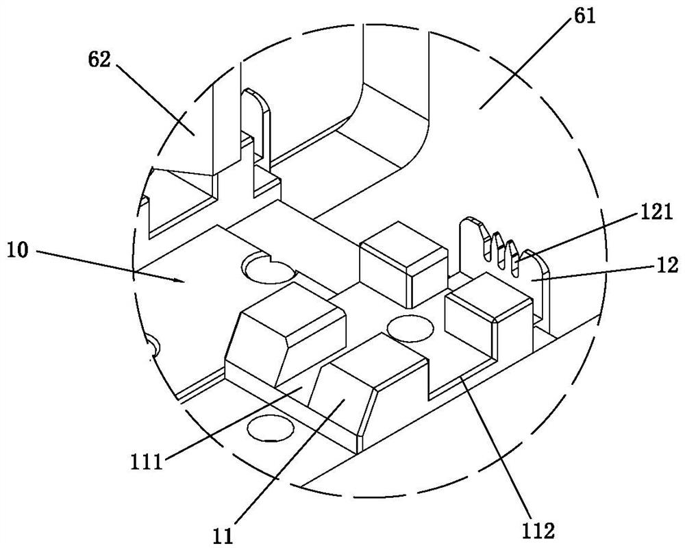
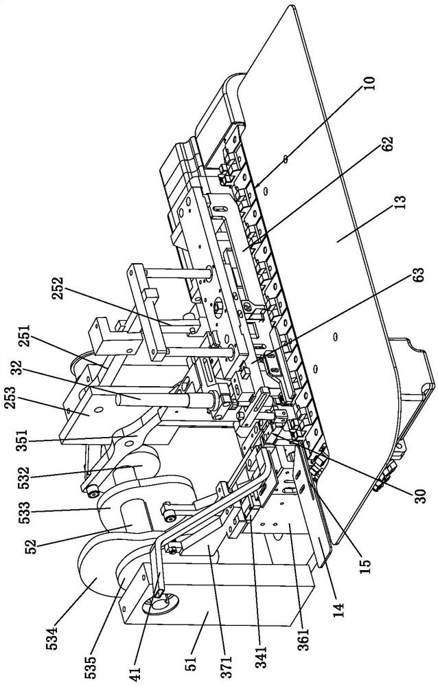
[0067] Please refer to Figure 1 to Figure 9 As shown, it shows the specific structure of the embodiment of the present invention.

[0068] A cam welding machine includes a conveying mechanism 10, a peeling mechanism 20, a welding mechanism 30, a joint feeding mechanism and a cam transmission mechanism 50; wherein:

[0069] The peeling mechanism 20, the welding mechanism 30 and the joint feeding mechanism are sequentially arranged on the rear side of the conveying mechanism 10 from left to right, and the cam transmission mechanism 50 is arranged behind the peeling mechanism 20 and the welding mechanism 30. The cam transmission mechanism 50 includes a seat body 51, a rotating shaft 52, a cam module and a driving device 54. The rotating shaft 52 extends left and right and is rotatably arranged on the seat body 51. The driving device 54 is drivingly connected to one end of the rotating shaft 52. The driving device 54 is connected to the rotating shaft 52 through a pulley, and th...


PUM


Abstract

The invention discloses a cam welding machine which comprises a conveying mechanism, a peeling mechanism, a welding mechanism, a connector feeding mechanism and a cam transmission mechanism. The cam transmission mechanism comprises a seat body, a rotating shaft, a cam module and a driving device, the driving device is in driving connection with the rotating shaft, and the cam module comprises first to fifth cams which are arranged on the rotating shaft at intervals left and right; the tool apron is connected to the first cam through a first transmission assembly, and the upper peeling knife is connected to the second cam through a second transmission assembly; the welding head is connected to the third cam through a third transmission assembly, the feeding base is connected to the fourth cam through a fourth transmission assembly, and the push rod is connected to the fifth cam through a fifth transmission assembly. Thus, through the design of the cam transmission mechanism, the first to fifth cams are in transmission connection with the first to fifth transmission assemblies, wire peeling, connector feeding and welding machining between the connector and the wire are achieved, the production efficiency is high, the electricity consumption of equipment is reduced, the cost is low, and the application range is wide.

Description

technical field [0001] The invention relates to the technology in the field of data line processing, in particular to a cam welding machine. Background technique [0002] With the continuous development of electronic technology, connectors, as a medium product for transmitting signals, are more and more widely used. Whether it is equipment for industrial production or mobile phones, computers, MP3s, etc. that people often use, connectors are used as a In the production process of the connector, the non-metallic outer layer of each branch body connection end of the wire is usually stripped and cut flat, and then matched with the connector for positioning and welding and fixing. However, the structure of the existing wire processing equipment is poor, and each process needs to be equipped with one or two powers to realize the stripping of the wire, the cutting operation and the feeding of the joint, the welding operation of the push and welding head, and the energy consumption...

Claims


Application Information

Patent Timeline
IPC IPC(8): H01R43/02
CPCH01R43/0263H01R43/02
Inventor 秦启洋唐红兵
Owner 深圳市帆与航电子科技有限公司
Why Eureka
Try Eureka