Multi-cable active unwinding type laying equipment

A technology for laying equipment and cables, which is applied in the field of multi-cable active unwinding laying equipment, which can solve the problems of inability to achieve cable traction, reduced unwinding capacity, and low work efficiency, so as to reduce the difficulty of laying, keep clean, The effect of reducing labor intensity

Active Publication Date: 2022-04-15
石家庄市森田电子通信有限公司
View PDF22 Cites 3 Cited by
  • Summary
  • Abstract
  • Description
  • Claims
  • Application Information

AI Technical Summary

Problems solved by technology

However, the work efficiency is low, and because most of the connected lines are relatively long, as the weight of the cable gradually increases, the unwinding capacity of the cable roll will gradually decrease under the action of traction, and when the unwinding reaches a certain distance After that, construction personnel or pulling equipment will not be able to achieve cable pulling operations
Moreover, when connecting power equipment, multiple cables are mostly used, and for the rational layout of the scene and subsequent maintenance operations, these cables need to be arranged side by side, so that each cable roll is unwound one by one, and then It is extremely inefficient and difficult to arrange these cables side by side
In some specific scenarios, it is necessary to wind multiple cables together to increase the connection strength between the cables, and to improve the tensile and shear resistance of the cables accordingly. Therefore, it is necessary to wrap multiple cables At present, there is no better way to achieve fast and efficient winding between cables and ensure stable transmission of cables

Method used


Image

  • Multi-cable active unwinding type laying equipment
  • Multi-cable active unwinding type laying equipment
  • Multi-cable active unwinding type laying equipment

Examples


Embodiment Construction

[0034] Preferred embodiments of the present invention will be described below in conjunction with the accompanying drawings. It should be understood that the preferred embodiments described here are only used to illustrate and explain the present invention, not to limit the present invention.

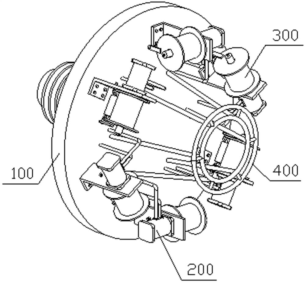
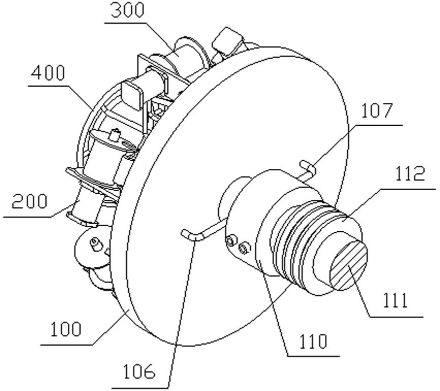
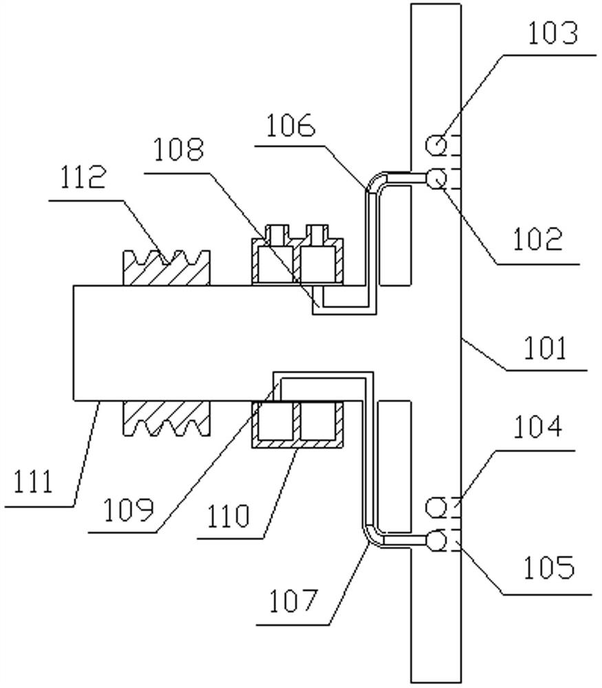
[0035] The invention discloses a multi-cable active unwinding type laying equipment, such as Figure 1-2 As shown, it includes a mounting base 100, a cable guiding mechanism 400 and a plurality of unwinding mechanisms 200, wherein a plurality of unwinding mechanisms 200 are installed on one end surface of the mounting base 100, and these unwinding mechanisms 200 are arranged along the circumference of the mounting base 100. Arranged evenly, a shaft 111 is configured at the end of the mounting seat 100 away from the unwinding mechanism 200, the shaft 111 is arranged at the center of the mounting seat 100, and the axis of the shaft 111 is perpendicular to the end face of the mounting seat...


PUM


Abstract

The invention discloses multi-cable active unwinding type laying equipment, which comprises a plurality of unwinding mechanisms which are uniformly mounted on the end surface of one end of a mounting seat along the circumferential direction of the mounting seat, cable rolls are mounted on the unwinding mechanisms, a shaft rod perpendicular to the end surface of the mounting seat is constructed at the center of one end, far away from the unwinding mechanisms, of the mounting seat, and the cable rolls are mounted on the shaft rod. A cable guiding mechanism is installed on the end face, on the same side as the unwinding mechanism, of the installation base. According to the invention, active unwinding of a plurality of cable coils is realized at the same time, cable laying is stably and efficiently carried out in cooperation with traction of constructors or traction equipment, the labor intensity of the constructors is reduced, corresponding problems caused by high-load operation of the traction equipment are avoided, and the cable laying device can be used for laying cables according to requirements of different scenes. The cables are laid side by side or wound, so that the scene is kept clean and tidy, and the laying difficulty is reduced. The cable laying device is suitable for the technical field of cable laying in power construction.

Description

technical field [0001] The invention belongs to the technical field of cable laying in electric power construction, and in particular relates to a multi-cable active unwinding laying equipment. Background technique [0002] In electric power construction, power equipment is mostly connected by cables, so the laying of cables is one of the indispensable and important links. At present, most of the cable laying methods are to pull one end of the cable coiled by the construction personnel or traction equipment, and then follow the construction personnel or traction equipment to advance according to the predetermined route, and then realize the cable laying operation. . However, the work efficiency is low, and because most of the connected lines are relatively long, as the weight of the cable gradually increases, the unwinding capacity of the cable roll will gradually decrease under the action of traction, and when the unwinding reaches a certain distance After that, construct...

Claims


Application Information

Patent Timeline
Patent Type & Authority Applications(China)
IPC IPC(8): H02G1/06B65H49/32B65H67/02B65H49/34B65H57/14
Inventor 张宏繁赵爱英
Owner 石家庄市森田电子通信有限公司
Why Eureka
Try Eureka