
Lamp switch switching structure and method

A lamp switch and switch technology, applied in the direction of electronic switches, electrical components, pulse technology, etc., can solve the problem of large lamp volume and achieve the effect of reducing the volume of lamps

Pending Publication Date: 2022-04-15
SHANGHAI AVIATION ELECTRIC
View PDF0 Cites 0 Cited by
  • Summary
  • Abstract
  • Description
  • Claims
  • Application Information

AI Technical Summary

Problems solved by technology

[0003] The purpose of the present invention is to overcome the problem of large volume of lamps in the prior art, and provide a new switch structure and method for lamps

Method used


Image

  • Lamp switch switching structure and method
  • Lamp switch switching structure and method
  • Lamp switch switching structure and method

Examples


Embodiment Construction

[0028] The present invention will be further described in detail below through specific embodiments in conjunction with the accompanying drawings. It should be noted here that the descriptions of these embodiments are used to help understand the present invention, but are not intended to limit the present invention. In addition, the technical features involved in the various embodiments of the present invention described below can be combined with each other as long as they do not constitute a conflict with each other.

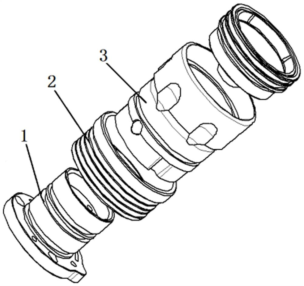
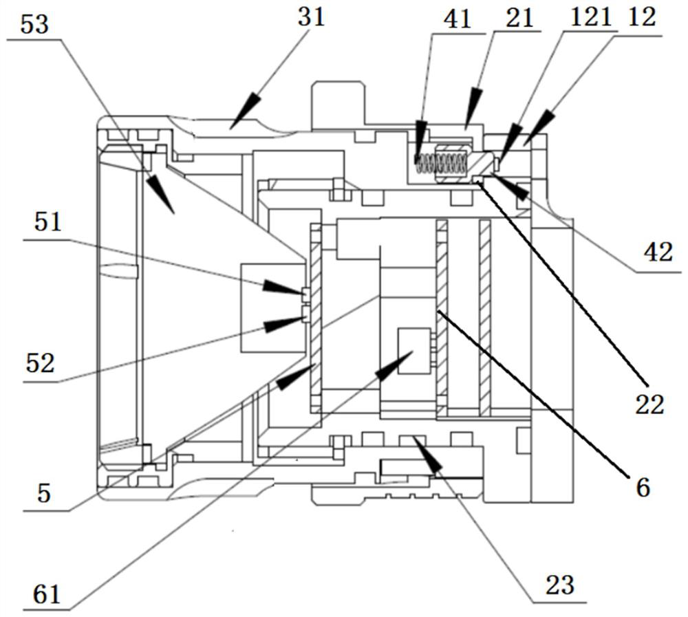
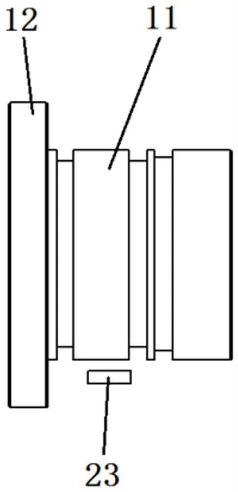
[0029] See Figures 1 to 11 , what is shown in the figure is a light switch switching structure.

[0030] The lamp switch switching structure is composed of a switch support 1, a switch outer ring 2, a lamp holder housing 3, an outer ring positioning component 4, a light source printed board 5 and a control printed board 6 and other components.

[0031] The switch support 1 has a support peripheral wall 11 and a support bottom wall 12 . The base bottom wall...


PUM


Abstract

The invention discloses a lamp switch switching structure and method. The lamp switch switching structure is composed of a switch support, a switch outer ring, a lamp holder shell, an outer ring positioning assembly, a light source printed board, a control printed board and the like. The lamp has the beneficial effects that various optical modes of the lamp are realized in an eccentric mode by utilizing the electromagnetic induction principle of the magnetic column and the Hall element.

Description

technical field [0001] The present invention relates to lamp lighting, in particular, a lamp switch switching structure and method. Background technique [0002] At present, in the field of military lighting, the same lamp is generally controlled by a processor to switch on and off two channels to achieve different modes of light output. Due to environmental adaptability, this design method is limited in its application occasions, and the way of hardware control such as processors makes the life of the lamp and the reliability of the work not high. Existing structures with more than two lighting modes are all realized through hardware control. The more modes, the corresponding increase in the number of light distribution lenses, the volume of the entire lamp doubles, the more the number of channels, the more failure forms, and the reliability drops significantly. Contents of the invention [0003] The object of the present invention is to overcome the problem of large vol...

Claims


Application Information

Patent Timeline
IPC IPC(8): H03K17/90
Inventor 刘杰曾庆兵李春晖张磊
Owner SHANGHAI AVIATION ELECTRIC
Learn More