
Light adjustment system for LED lamp

An LED lamp and LED driver technology, applied in the field of LED lighting, can solve the problems of noise, thyristor switch and LC flickering audio, etc., and achieve the effect of reducing the production cost and the volume of the lamp

Inactive Publication Date: 2017-08-18
SHENZHEN INTELTRON INTELLIGENT SCI & TECH CO LTD
View PDF7 Cites 1 Cited by
  • Summary
  • Abstract
  • Description
  • Claims
  • Application Information

AI Technical Summary

Problems solved by technology

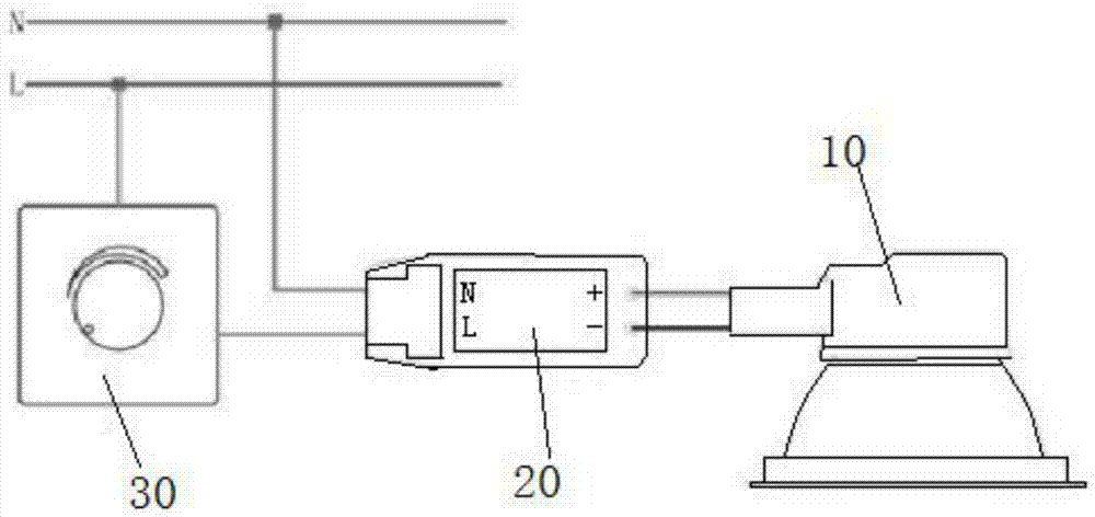
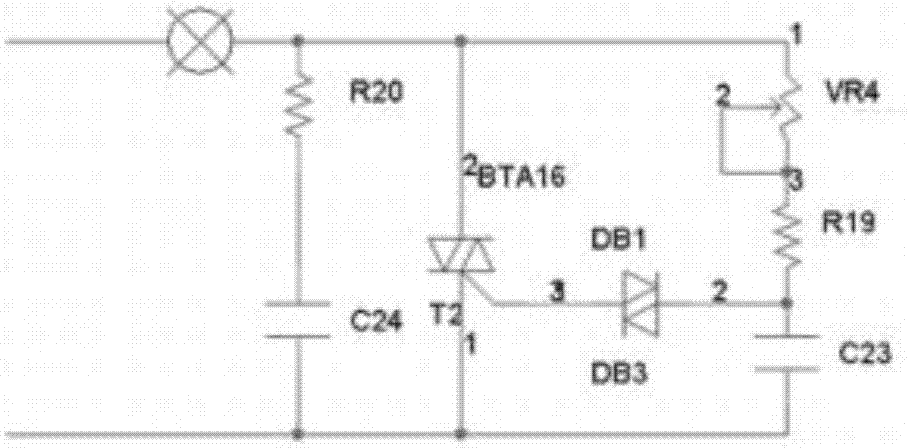
[0004] In order to overcome the above-mentioned deficiencies of the prior art, the present invention provides an LED lamp dimming system, which uses a pure impedance circuit to solve the problem of flicker and audio noise caused by the resonance between the existing thyristor switch and LC

Method used


Image

  • Light adjustment system for LED lamp
  • Light adjustment system for LED lamp
  • Light adjustment system for LED lamp

Examples


Embodiment Construction

[0018] In order to make the purpose, technical solutions and advantages of the embodiments of the present invention clearer, the technical solutions in the embodiments of the present invention will be clearly and completely described below in conjunction with the drawings in the embodiments of the present invention. Obviously, the described embodiments It is a part of embodiments of the present invention, but not all embodiments. The components of the embodiments of the invention generally described and illustrated in the figures herein may be arranged and designed in a variety of different configurations. Accordingly, the following detailed description of the embodiments of the invention provided in the accompanying drawings is not intended to limit the scope of the claimed invention, but merely represents selected embodiments of the invention. Based on the embodiments of the present invention, all other embodiments obtained by persons of ordinary skill in the art without cre...


PUM


Abstract

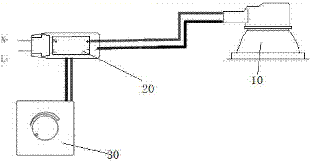
The invention discloses a light adjustment system for an LED lamp, and the system comprises an LED drive power module. The interior of the LED drive power module is provided with a voltage control module, and the voltage control module is connected with a light adjuster which is used for tuning the output voltage of the LED drive power module. The output end of the LED drive power module is connected with the LED lamp, and the input voltage of the LED lamp is controlled by the voltage control module. The interior of the LED lamp is not provided with an inductor and a capacitor, thereby solving a flickering problem caused by the resonance of a conventional silicon-controlled switch, an inductor and a capacitor.

Description

technical field [0001] The invention relates to LED lighting technology, in particular to an LED light dimming system. Background technique [0002] At present, the common dimming method of LED lighting is the thyristor dimming method, but the thyristor dimming method often causes flickering problems and limits the adjustable dimming range. Aiming at the problems existing between the compatibility of current thyristor (TRIAC) dimmers and LED dimming, the existing technology is mainly to rectify the LED power drive, but when rectifying the LED power drive, in order to be compatible with the dimmers on the market The optical device needs to add a large number of electronic components, and the heat dissipation of the power supply must be handled by potting glue. After adding a large number of components to the LED power driver, the volume of the power supply will increase, and the cost of the power supply will also increase greatly. In the case of volume and increased cost, th...

Claims


Application Information

Patent Timeline
IPC IPC(8): H05B33/08H05B44/00
CPCH05B45/00H05B45/395H05B45/12
Inventor 唐波张林王义向杨董晓勇
Owner SHENZHEN INTELTRON INTELLIGENT SCI & TECH CO LTD
Learn More