Reflection type light projector device

An optical device and reflective technology, applied in the direction of reflectors, lighting devices, and components of lighting devices, etc., can solve the problems of low improvement space, bulky lamps, and inability to emit reflected light, and achieve the effect of reducing the volume of lamps

Inactive Publication Date: 2007-10-31
IND TECH RES INST +1
View PDF4 Cites 6 Cited by
  • Summary
  • Abstract
  • Description
  • Claims
  • Application Information

AI Technical Summary

Problems solved by technology

[0005] Please refer to FIG. 3, US Patent No. 5,136,483 "Illuminating device", which proposes a vehicle lamp, which includes a reflector 16, a plurality of light-emitting diodes 14 placed flat on the inner annular side wall of the reflector 16, And heat dissipation fin 19, the light that described light-emitting diode 14 sends can produce parallel light through the reflection of the curved surface bottom of reflector 16; A small part can be reflected by the reflector 16 to produce parallel light. As for the light in other light angle ranges, part of it is scattered out of the reflector 16 at undesired light angles, and some of the light is reflected multiple times inside the reflector 16. Therefore, its light extraction efficiency is not good, and it cannot produce highly collimated parallel light rays. Although the above-mentioned problems can be improved by changing the design of the reflector 16, the design is extremely difficult and there is room for improvement. not high
[0006] Please refer to FIG. 4, US Patent No. 5,838,247 "Solid state light system".

Method used


Image

  • Reflection type light projector device
  • Reflection type light projector device
  • Reflection type light projector device

Examples


Embodiment Construction

[0050] The technical means and effects used by the present invention to achieve the purpose will be described below with reference to the attached drawings.

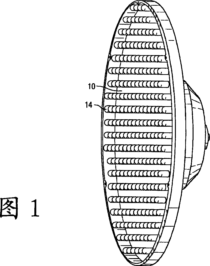
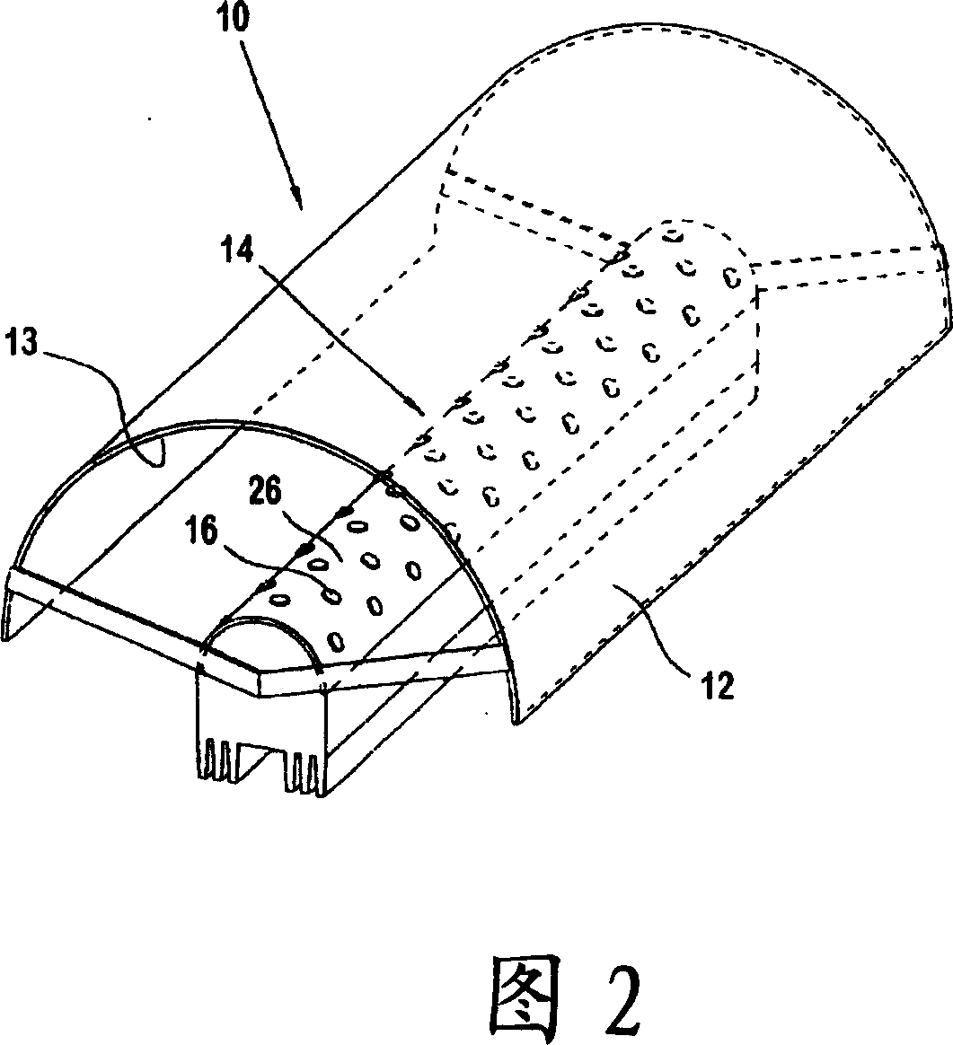
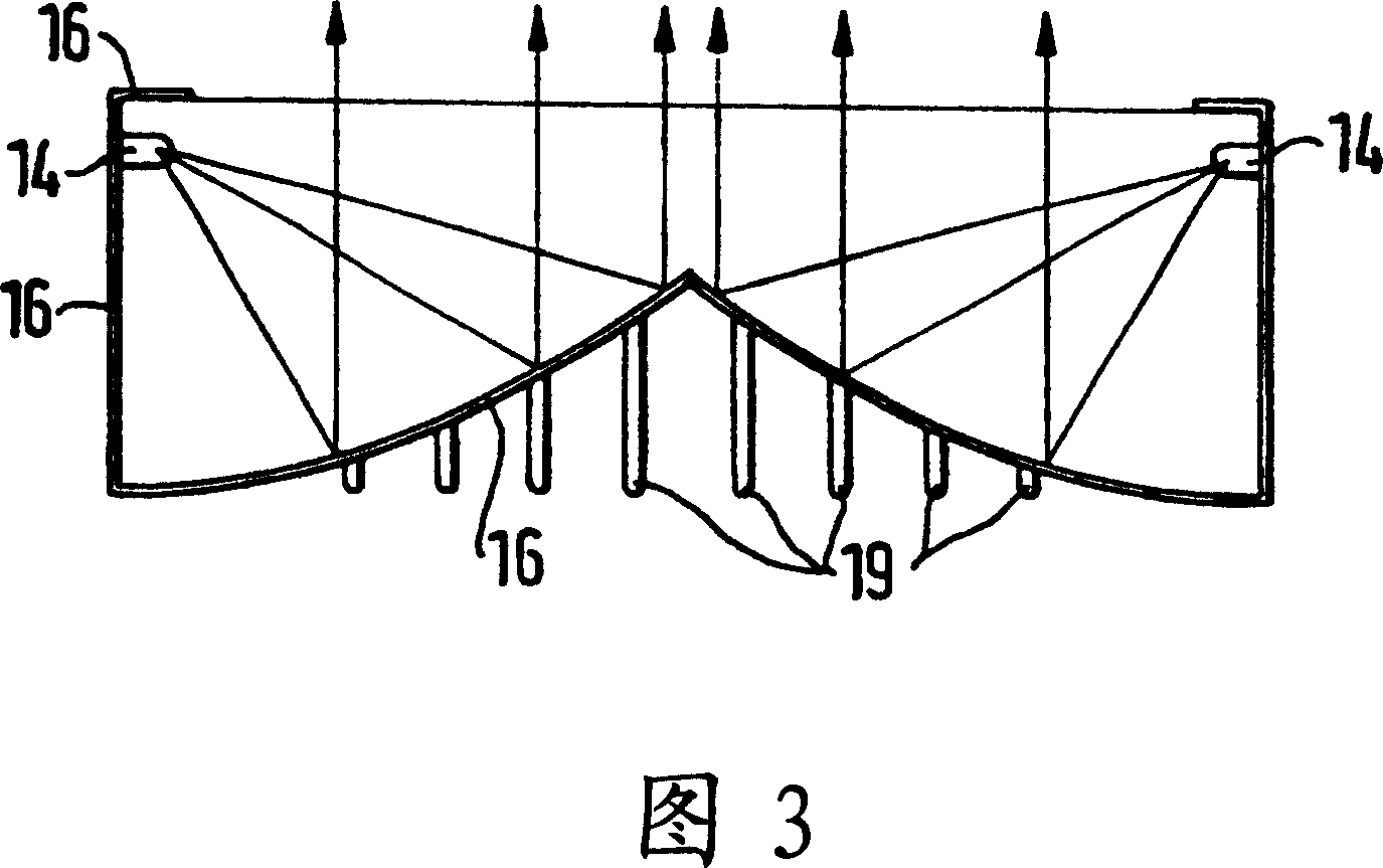
[0051] Please refer to FIG. 5, a reflective light projection device provided by the present invention includes a light guide cover 10 and at least one light source 20. The light guide cover 10 is made of a material with reflective properties. The inner sidewall of the light guide cover 10 can be provided with a reflective layer (not shown) to improve the light reflectivity, the material of the reflective layer can be the existing reflective diffusion film used in flat panel displays, or can be made of Metal materials such as aluminum or electroless nickel are formed by electroplating. The light source 20 is preferably a directional light source with a certain light output angle, such as a light emitting diode. The light guide cover 10 has a bottom 11 and at least one light output port. 12. A feature of the present invent...


PUM


Abstract

The invention is a reflection-type light-projecting device, comprising a light-guiding cover with reflecting characteristic and a directional light source, wherein the light-guiding cover has a reflection surface of Fresnel structure which uses Fresnel lens principle and converts the geometrical reflection surface to an equivalent reflection surface to be a plane, a chamber or a combination, the reflection surface of Fresnel structure is arranged at the bottom of the light-guiding cover, the light source is arranged on the side wall of the light-guiding cover, adjusting the light direction to form a certain engageable angle with the Fresnel structure can make the reflecting light emitted in certain angle from the light-guiding cover, to generate collimated light with high efficiency and high alignment.

Description

technical field [0001] The present invention relates to a light projection device, in particular to a Fresnel lens principle, which converts a geometric reflective surface into an equivalent reflective surface, and cooperates with a light source that controls the luminous angle to produce high efficiency and high collimation. A light projection device for parallel rays. Background technique [0002] The light sources of traditional lamps can be roughly divided into two types: point light sources and line light sources. Tungsten filament lamps and energy-saving bulbs are point light sources, while fluorescent tubes are line light sources. When the above two light sources emit light, they emit light in a radial manner. The disadvantage of emitting outward is that it is large in size. Due to the main advantage of small size, light-emitting diodes (LEDs) have been continuously developed and applied to lighting tools in recent years. Moreover, due to the continuous improvement of...

Claims


Application Information

Patent Timeline
IPC IPC(8): F21V7/10F21V8/00F21Y101/02F21Y115/10
Inventor 林建宪王健全赖杰隆许修真孙翊庭
Owner IND TECH RES INST
Why Eureka
Try Eureka