Fire-fighting equipment storage box convenient to store and take
A technology for firefighting equipment and storage boxes, applied in fire rescue and other directions, can solve problems such as easy collision and inability to take out quickly, and achieve the effect of extending service life, speeding up the efficiency of fire fighting, and being easy to take out and use.
- Summary
- Abstract
- Description
- Claims
- Application Information
AI Technical Summary
Problems solved by technology
Method used
Image
Examples
Embodiment 1
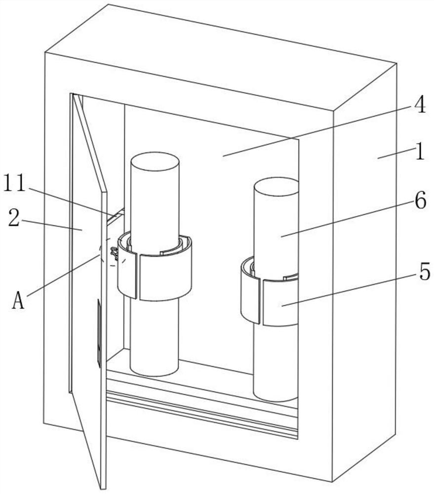
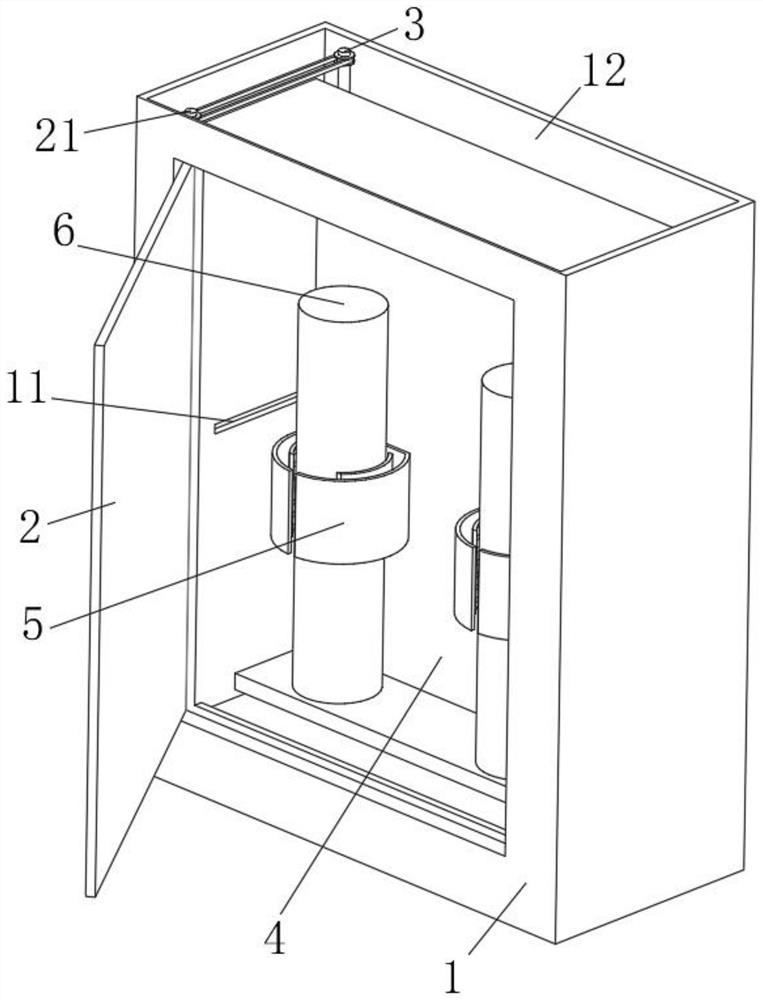
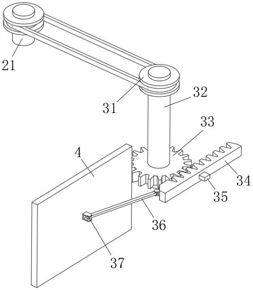
[0031] refer to Figure 1-5 , a storage box for fire-fighting equipment that is easy to access, includes a storage box body 1, which is convenient for storing fire extinguishers 6, and the inner wall of the storage box body 1 is symmetrically provided with chute 11, which is used to limit the moving track of the moving plate 4, and the storage box body 1 is provided with a cavity 12 inside, and the outer surface of the storage box body 1 is rotatably connected with a protective door 2 to protect the inside of the storage box body 1. The upper and lower ends of the protective door 2 are fixedly connected with door shafts 21, and the cavity 12 is provided with two sets of push-out components 3, and the interior of the storage box body 1 is provided with a moving plate 4, which is convenient to drive the fire extinguisher 6 to move. The outer surface of the moving plate 4 is provided with two sets of grooves 41, and the two sets of grooves 41 A protective assembly 5 is provided i...
Embodiment 2
[0036] Such as Figure 1-5 As shown, this embodiment is basically the same as Embodiment 1. Preferably, the ends of the two groups of door shafts 21 that are far away from each other penetrate through the outer surface of the storage box body 1 and extend to the inside of the cavity 12, and the door shafts 21 are connected to each other. Both ends away from each other are rotatably connected with the inner wall of the cavity 12 .
[0037] In this embodiment, the door shaft 21 is provided so that when the protective door 2 is opened or closed, it can drive the pulley set 31 to start rotating.
Embodiment 3
[0039] Such as Figure 1-5 As shown, this embodiment is basically the same as Embodiment 1. Preferably, the upper and lower ends of the round rod 32 penetrate the outer surface of the pulley set 31, and the upper and lower ends of the round rod 32 rotate with the inner wall of the cavity 12. connect.
[0040] In this embodiment, the pulley set 31 is provided so that when the protective door 2 is opened, the round bar 32 can be driven to rotate by the action of the pulley set 31, and the moving plate 4 can be driven to start moving.
PUM
 Abstract
Description
Claims
Application Information
 - R&D
- Intellectual Property
- Life Sciences
- Materials
- Tech Scout
- Unparalleled Data Quality
- Higher Quality Content
- 60% Fewer Hallucinations
Browse by: Latest US Patents, China's latest patents, Technical Efficacy Thesaurus, Application Domain, Technology Topic, Popular Technical Reports.
© 2025 PatSnap. All rights reserved.Legal|Privacy policy|Modern Slavery Act Transparency Statement|Sitemap|About US| Contact US: help@patsnap.com


