
Cold film laminating machine with high-precision film cutting function

A high-precision, cold-lamination technology, applied in the field of high-precision film-cutting cold-laminators, can solve the problems of reduced production efficiency, film offset, and poor lamination accuracy of cold-laminators

Pending Publication Date: 2022-04-19
佛山市高明基业冷轧钢板有限公司
View PDF8 Cites 0 Cited by
  • Summary
  • Abstract
  • Description
  • Claims
  • Application Information

AI Technical Summary

Problems solved by technology

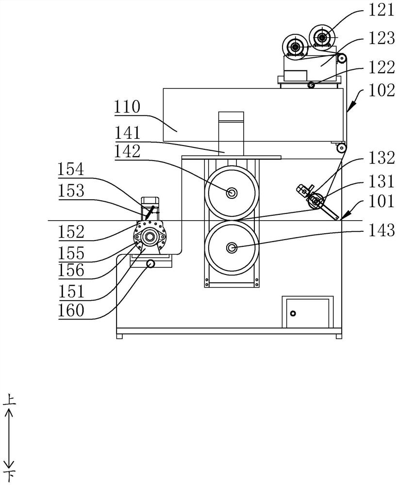
[0002] Coated strip steel is a widely used metal sheet. At present, the coating methods on the surface of strip steel can be divided into cold coating and hot coating. The traditional cold coating machine will first cut the film through the cutting structure before coating. After cutting, the cut film is covered on the steel strip. However, first of all, because the film needs to be transported for a certain distance after it is cut and then touches the steel strip, the film may be offset, which leads to the failure of the traditional cold laminating machine. The coating accuracy is poor, and the strip steel needs to be cut after coating, or needs to be re-coated, which reduces production efficiency

Method used


Image

  • Cold film laminating machine with high-precision film cutting function
  • Cold film laminating machine with high-precision film cutting function
  • Cold film laminating machine with high-precision film cutting function

Examples


Embodiment Construction

[0020] The idea, specific structure and technical effects of the present invention will be clearly and completely described below in conjunction with the embodiments and accompanying drawings, so as to fully understand the purpose, features and effects of the present invention. Apparently, the described embodiments are only some of the embodiments of the present invention, rather than all of them. Based on the embodiments of the present invention, other embodiments obtained by those skilled in the art without creative efforts belong to The protection scope of the present invention. In addition, all connection relationships mentioned in this article do not refer to the direct connection of components, but mean that a better connection structure can be formed by adding or reducing connection accessories according to specific implementation conditions. The various technical features in the present invention can be combined interactively on the premise of not conflicting with each...


PUM


Abstract

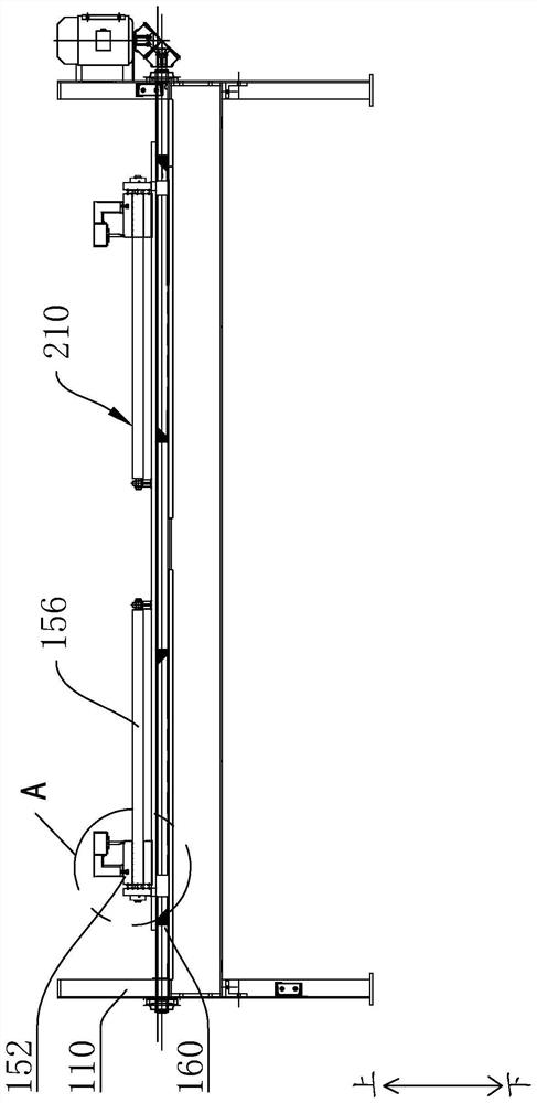
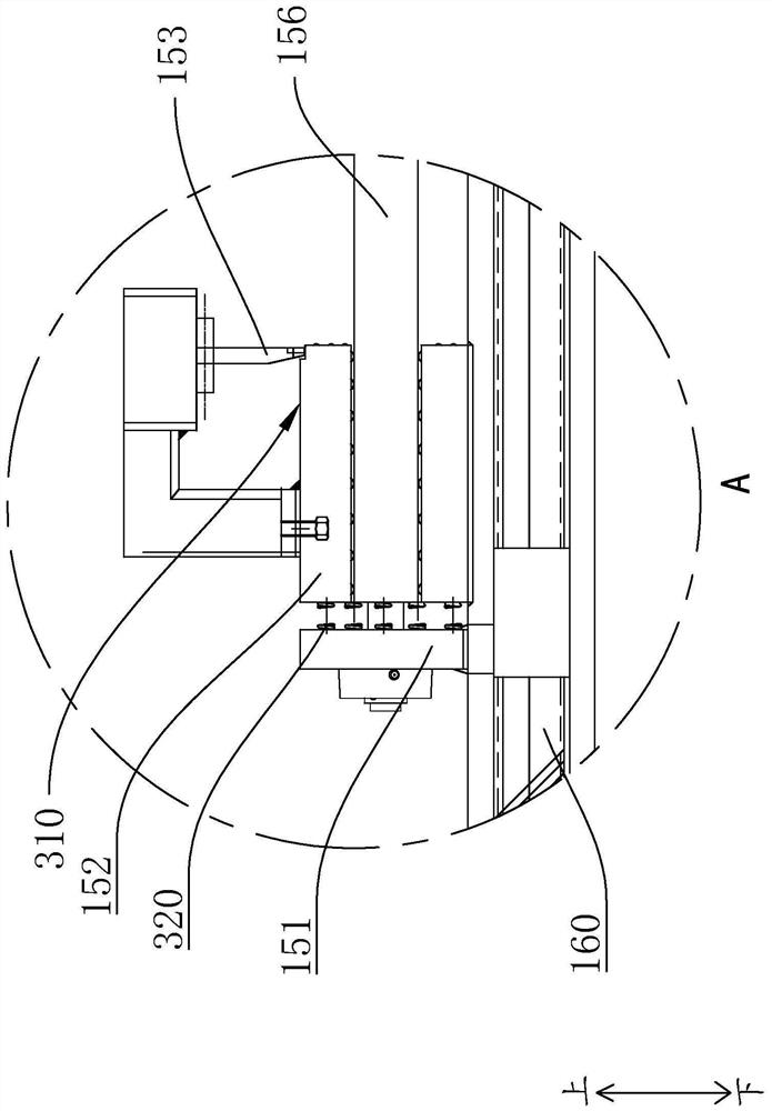
The invention discloses a cold film laminating machine with a high-precision film cutting function. The cold film laminating machine comprises a rack, the conveying device is provided with a conveying surface; the film covering device is arranged on the rack, the film covering device is provided with a film covering gap, and the conveying face penetrates through the film covering gap; the cutting structure is located on the conveying downstream of the conveying face relative to the film covering device and comprises mounting vehicles, the mounting vehicles are arranged on the rack in a sliding mode, the two mounting vehicles are horizontally arranged in a spaced mode in the direction perpendicular to the conveying direction of the conveying face, the mounting vehicles can slide along the track perpendicular to the conveying direction of the conveying face, and film supporting blocks are synchronously arranged on the mounting vehicles; the two film supporting blocks surround the two sides of the conveying face, the top faces of the film supporting blocks are cutting faces, the cutting faces are higher than the conveying face, the film supporting blocks are provided with cutting knives, the cutting knives are located above the cutting faces, cutting edges of the cutting knives extend downwards towards the cutting faces, it is guaranteed that the part, exceeding the strip steel, of the film can directly stretch into the cutting faces, and the film supporting blocks bear the part of the film. And the cutting of the cutter is facilitated.

Description

technical field [0001] The invention relates to the field of a high-precision film-cutting cold laminating machine, in particular to a high-precision film-cutting cold laminating machine. Background technique [0002] Coated strip steel is a widely used metal sheet. At present, the coating methods on the surface of strip steel can be divided into cold coating and hot coating. The traditional cold coating machine will first cut the film through the cutting structure before coating. After cutting, the cut film is covered on the steel strip. However, first of all, because the film needs to be transported for a certain distance after it is cut and then touches the steel strip, the film may be offset, which leads to the failure of the traditional cold laminating machine. The coating accuracy is poor, and the strip steel needs to be cut after coating, or needs to be re-coated, which reduces production efficiency. Contents of the invention [0003] The purpose of the present inv...

Claims


Application Information

Patent Timeline
IPC IPC(8): B29C63/02
CPCB29C63/02B29C63/0004
Inventor 曾志涛胡可柱陈志方
Owner 佛山市高明基业冷轧钢板有限公司
Learn More