Drainage groove for road construction

A technology for road construction and drainage tanks, which is applied in the direction of roads, roads, and sewage discharge, etc. It can solve problems such as inconvenient construction, inability to be well discharged, delaying construction progress and construction quality, and achieves the effect of convenient cleaning

Pending Publication Date: 2022-04-19
匡海鑫
View PDF6 Cites 0 Cited by
  • Summary
  • Abstract
  • Description
  • Claims
  • Application Information

AI Technical Summary

Problems solved by technology

[0002] Road construction is the front of a city's development. Only good roads can bring good economic development to a city. At present, road construction projects are mainly carried out in sunny weather. Construction must be stopped when it encounters rainy days. It is necessary to wait for the last three to five days until the pavement soil is completely dry before re-construction. The main reason for this is that the current road construction lacks good drainage equipment, and the rainwater cannot be well discharged after the road surface is wet ( The rainwater has stagnated on the road surface for a long time, and the rainwater penetration capacity of the road surface is generally very slow), so we can only wait for the road surface to dry naturally before construction, which will greatly delay the construction progress and construction quality for a long time
[0003] Moreover, when the rainwater is collected, a reservoir must be dug on the bottom surface, which leads to many inconveniences in the later construction.

Method used


Image

  • Drainage groove for road construction
  • Drainage groove for road construction
  • Drainage groove for road construction

Examples


Embodiment Construction

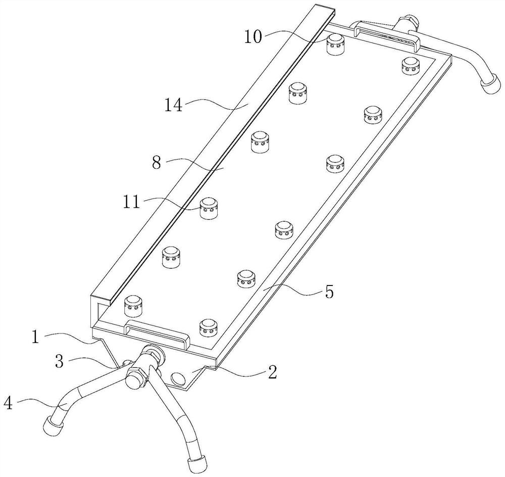
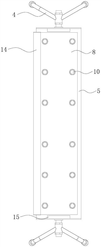
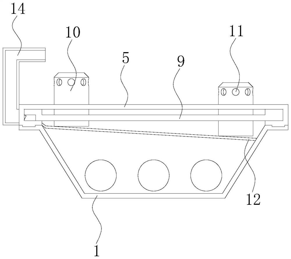
[0024] Such as Figure 1-7 As shown, a drainage channel for road construction includes a tank body 1, the front and rear ends of the tank body 1 are fixedly equipped with sealing plates 2, two sealing plates 2 seal the front and rear ends of the tank body 1, and the two sealing plates 2 The bottom of the tank is provided with three water holes 3, the sealing plate 2 provided on the tank body 1 can connect the two sets of devices together, the water holes 3 can communicate with the waterway, and the front and rear ends of the sealing plate 2 are provided with brackets 4, The sealing plate 2 and the support 4 are fixed by nuts, the sealing plate 2 can rotate relative to the support 4, the upper end of the support 4 is provided with a sleeve, and the sleeve and the sealing plate 2 are connected by threaded rods, and the two nuts are distributed in the sleeve On the front and rear sides of the cylinder, the nuts are sleeved on the threaded rods to fix the sleeve. The bracket 4 can...


PUM


Abstract

The invention provides a drainage channel for road construction, and relates to the field of road construction. The drainage tank for road construction comprises a tank body, sealing plates are fixedly installed at the front end and the rear end of the tank body and seal the front end and the rear end of the tank body, three water through holes are formed in the bottom of each sealing plate, supports are arranged at the front end and the rear end of each sealing plate, and the sealing plates and the supports are fixed through nuts. A frame is arranged above the groove body, the left end and the right end of the bottom of the frame are in sliding connection with the left side and the right side of the upper end of the groove body respectively, and the front end and the rear end of the frame are limited by the two sealing plates. According to the drainage tank for road construction, by arranging the tank body, the water permeable column, the first isolation plate, the second isolation plate and the like, the effects of collecting rainwater and preventing a large amount of silt from entering can be achieved, and the problems that in the prior art, rainwater cannot be well collected, silt is difficult to block even if a water collecting device is adopted, and then blockage is caused are solved.

Description

technical field [0001] The invention relates to the field of road construction, in particular to a drainage tank for road construction. Background technique [0002] Road construction is the front of a city's development. Only good roads can bring good economic development to a city. At present, road construction projects are mainly carried out in sunny weather. Construction must be stopped when it encounters rainy days. It is necessary to wait for the last three to five days until the pavement soil is completely dry before re-construction. The main reason for this is that the current road construction lacks good drainage equipment, and the rainwater cannot be well discharged after the road surface is wet ( Rainwater stagnates on the road surface for a long time, and the rainwater penetration capacity of the road surface is generally very slow), so we can only wait for the road surface to dry naturally before construction, which will greatly delay the construction progress a...

Claims


Application Information

Patent Timeline
Patent Type & Authority Applications(China)
IPC IPC(8): E03F5/04E03F5/14E03F1/00E01C11/22
CPCE03F5/0401E03F5/0404E03F5/14E03F1/003E01C11/227
Inventor 匡海鑫
Owner 匡海鑫
Why Eureka
Try Eureka