Heat preservation device for building water supply and drainage and heating and ventilation engineering

A technology for HVAC engineering and thermal insulation devices, which is applied in the directions of thermal insulation, pipeline protection through thermal insulation, pipeline protection, etc. It can solve the problems of falling off and loosening of thermal insulation materials, affecting the effect of pipeline thermal insulation, etc., so as to increase the contact area and service life. Long-lasting, increased stability effect

Pending Publication Date: 2022-04-19
朱孟标
View PDF1 Cites 0 Cited by
  • Summary
  • Abstract
  • Description
  • Claims
  • Application Information

AI Technical Summary

Problems solved by technology

[0005] 1. In the process of using the thermal insulation device for building water supply and drainage and HVAC engineering, there is no structure that can automatically adjust the tightness of the thermal insulation material, so that the thermal insulation device for building water supply and drainage and HVAC engineering may be damaged during long-term use. The insulation material falls off, which affects the normal insulation effect of the pipeline;
[0006] 2. The thermal insulation device for building water supply and drainage and HVAC engineering lacks a reinforced structure during use, so that the thermal insulation device for building water supply and drainage and HVAC engineering may cause damage to the structure of the thermal insulation device itself during use. loose, thus affecting the normal use of the insulation device,

Method used


Image

  • Heat preservation device for building water supply and drainage and heating and ventilation engineering
  • Heat preservation device for building water supply and drainage and heating and ventilation engineering
  • Heat preservation device for building water supply and drainage and heating and ventilation engineering

Examples


Embodiment Construction

[0040] The following will clearly and completely describe the technical solutions in the embodiments of the present invention with reference to the accompanying drawings in the embodiments of the present invention. Obviously, the described embodiments are only some, not all, embodiments of the present invention. Based on the embodiments of the present invention, all other embodiments obtained by persons of ordinary skill in the art without making creative efforts belong to the protection scope of the present invention.

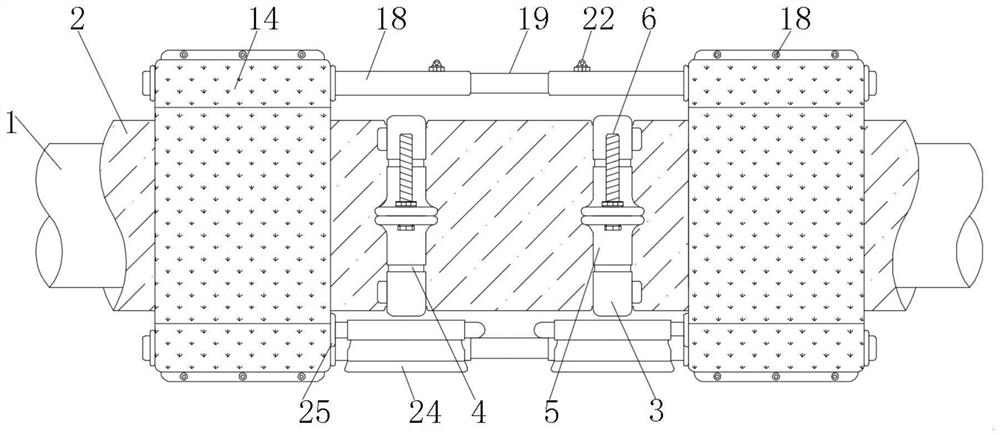
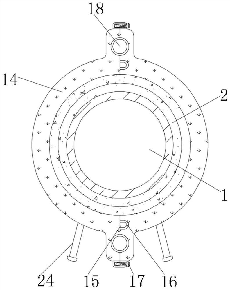
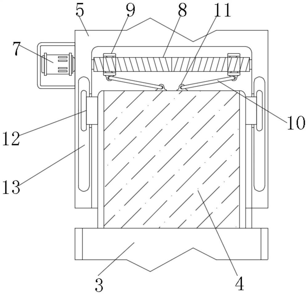
[0041] see Figure 1-5 , the present invention provides a technical solution: a thermal insulation device for building water supply and drainage and HVAC engineering, comprising: a pipeline 1, the surface of the pipeline 1 is equipped with a thermal insulation layer 2; , and the beam plate 3 is made of flexible metal, and one end of the beam plate 3 is fixedly connected with a receiving plate 4, and the surface of the receiving plate 4 is sleeved with a fixed ...


PUM


Abstract

The invention discloses a heat preservation device for building water supply and drainage and heating and ventilation engineering, which comprises a pipeline, a heat preservation layer and a heat preservation layer, and the bundle plate is connected to the surface of the heat preservation layer and is made of a flexible metal material, one end of the bundle plate is fixedly connected with a bearing plate, and the surface of the bearing plate is sleeved with a fixing plate made of a flexible metal material. According to the heat preservation device for the building water supply and drainage and heating and ventilation engineering, an operator fixes two fixing plates on the surface of a heat preservation layer through fixing threaded rods, then a forward and reverse motor is started, and two shaft sleeves are driven to move on the surfaces of two-way threaded rods; then the linkage rod forms a linkage structure on one side of the bearing plate through a two-way threaded rod in the shaft sleeve, the bearing plate forms a sliding connection structure at the opening of the fixing plate through a limiting block, and the tightness of the bearing plate at the opening end of the fixing plate is adjusted, so that the bundle plate is tightly connected with the heat preservation layer; therefore, the purpose of automatically adjusting the tightness degree is achieved.

Description

technical field [0001] The invention relates to the technical field of thermal insulation devices, in particular to a thermal insulation device for building water supply and drainage and HVAC engineering. Background technique [0002] Insulation pipe is the abbreviation of heat insulation pipe. The heat preservation pipe is used for the transportation of liquid, gas and other media. It not only has advanced technology and practical performance that are incomparable to traditional trenches and overhead pipelines, but also has significant social and economic benefits, and is also a powerful measure for heating and energy saving; [0003] For example, the publication number CN202022387664.1 is a thermal insulation device for building water supply and drainage and HVAC engineering, including a first thermal insulation shell and a second thermal insulation shell, the first thermal insulation shell is located directly above the second thermal insulation shell, and the first therma...

Claims


Application Information

Patent Timeline
Patent Type & Authority Applications(China)
IPC IPC(8): F16L59/02F16L59/12
CPCF16L59/02F16L59/12
Inventor 朱孟标陶雅舒汪光峰
Owner 朱孟标
Why Eureka
Try Eureka