A rotary shaft conductive structure for a rotary welding device

A technology of conductive structure and welding device, applied in rolling contact bearings, rotating bearings, bearings, etc., can solve the problems of cable winding damage, grounded rotor stuck, unable to rotate, etc., to improve insulation isolation and ensure stability Contact and avoid the effect of vibration

Active Publication Date: 2022-06-24
王俊霞
View PDF6 Cites 0 Cited by
  • Summary
  • Abstract
  • Description
  • Claims
  • Application Information

AI Technical Summary

Problems solved by technology

Although this method is simple, it is easy to cause damage to the cable winding, and the loss of the cable is very large
Another is to use ordinary grounded rotors, but the grounded rotors are prone to heat and deformation, and with the rotation of the workpiece, the grounded rotors will be stuck after working for a period of time and cannot rotate.
[0005] Therefore, if the method of directly fixing the ground wire on the workpiece for welding is labor-intensive, the work efficiency is low, and the service life of the cable is short.
If an ordinary grounded rotor is used, not only the quality of the product will be affected, but the high temperature will also pose a threat to the safety of production workers

Method used


Image

  • A rotary shaft conductive structure for a rotary welding device
  • A rotary shaft conductive structure for a rotary welding device
  • A rotary shaft conductive structure for a rotary welding device

Examples


preparation example Construction

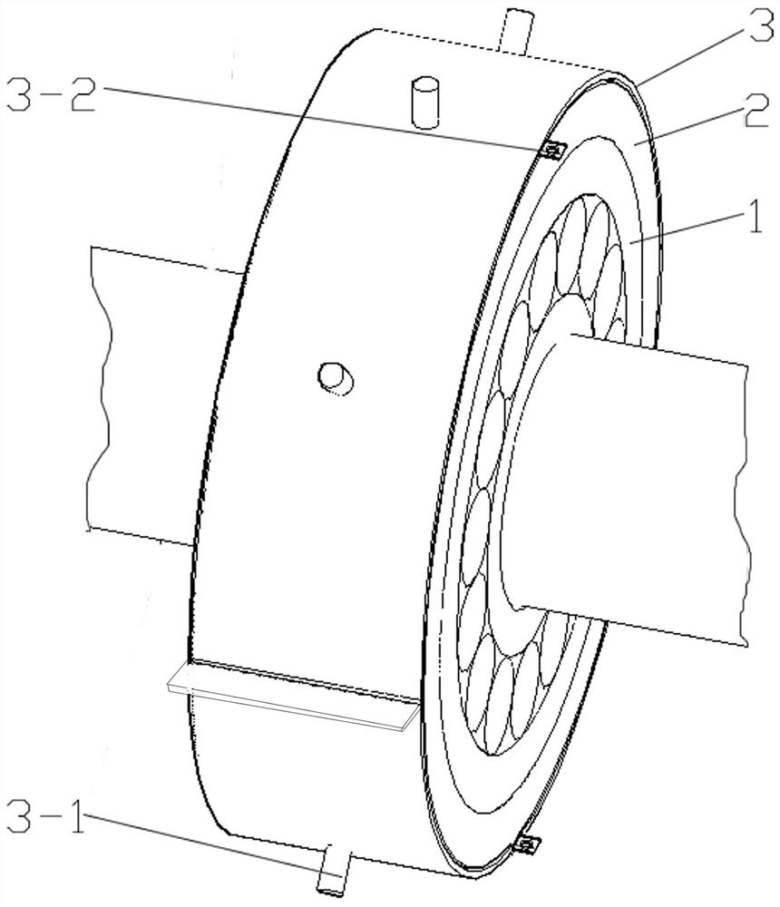
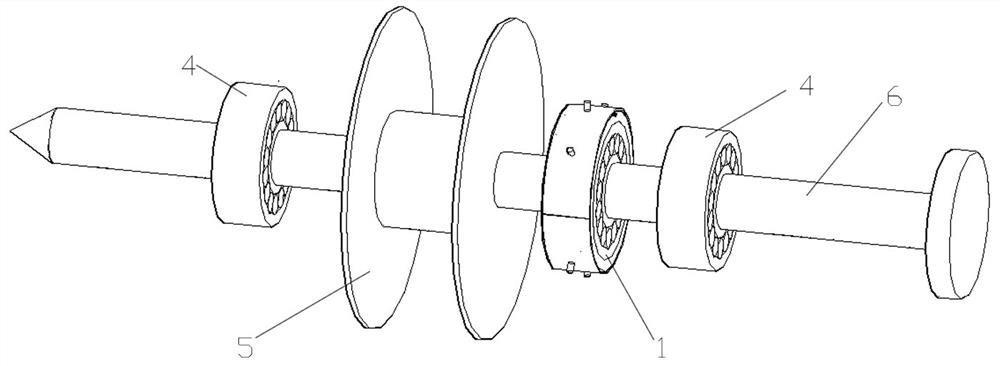
[0021] A rotary shaft conductive structure for a rotary welding device, the rotary shaft conductive structure is arranged at the rotary shaft 6 of the rotary welding device, the rotary shaft conductive structure includes a rolling bearing 1, and a conductive rubber sleeve 2 and a conductive copper sheet are arranged on the outer ring of the rolling bearing 1 3. The conductive rubber sleeve 2 is sandwiched between the outer ring of the rolling bearing 1 and the conductive copper sheet 3. The conductive copper sheet 3 is an annular structure composed of upper and lower semi-circular arc sheets. The conductive copper sheet 3 is provided with There are conductive joints 3-2, mounting holes are punched on the conductive copper sheet 3, and positioning posts 3-1 are installed at the mounting holes. The conductive rubber sleeve 2 sequentially includes a tubular material layer, an adhesive layer and a metal layer from the inside to the outside. In the mesh layer, metal powder is distri...

Embodiment 1

[0030] A rotary shaft conductive structure for a rotary welding device, the rotary shaft conductive structure is arranged at the rotary shaft 6 of the rotary welding device, the rotary shaft conductive structure includes a rolling bearing 1, and a conductive rubber sleeve 2 and a conductive copper sheet are arranged on the outer ring of the rolling bearing 1 3. The conductive rubber sleeve 2 is sandwiched between the outer ring of the rolling bearing 1 and the conductive copper sheet 3. The conductive copper sheet 3 is an annular structure composed of upper and lower semi-circular arc sheets. The conductive copper sheet 3 is provided with There are conductive joints 3-2, mounting holes are punched on the conductive copper sheet 3, and positioning posts 3-1 are installed at the mounting holes. The conductive rubber sleeve 2 sequentially includes a tubular material layer, an adhesive layer and a metal layer from the inside to the outside. In the mesh layer, metal powder is distri...

Embodiment 2

[0034] On the basis of the first embodiment, this embodiment mainly changes the formula of the conductive rubber sleeve 2 and the specific parameters of the process, and the specific description is as follows:

[0035] The conductive rubber sleeve 2 is prepared by the following steps; metal powder and additives are put into a mixer according to a set ratio, and after dispersion and stirring, the conductive material is prepared; the mixed silicone rubber material is passed through an extruder It is extruded into a tubular material, wherein the extrusion pressure is 4MPA, and the extrusion temperature is 185°C; the adhesive layer raw materials are mixed and stirred according to a certain ratio, and the mixed adhesive layer silica gel raw material is uniformly coated on the obtained product in the previous step. The inner and outer surfaces of the tubular material were prepared for use; metal mesh was laid on the inner and outer surfaces of the tubular material layer obtained abov...


PUM


Abstract

The invention discloses a rotating shaft conductive structure for a rotary welding device. The rotating shaft conductive structure is arranged at the rotating shaft of the rotary welding device. The rotating shaft conductive structure includes a rolling bearing, and a conductive rubber sleeve and a conductive copper sheet are arranged on the outer ring of the rolling bearing. The conductive rubber sleeve is sandwiched between the outer ring of the rolling bearing and the conductive copper sheet. The conductive copper sheet is an annular structure composed of upper and lower semicircular arc-shaped sheets. The conductive copper sheet is provided with a conductive joint. On the conductive copper sheet A mounting hole is punched, and a positioning column is installed at the mounting hole. The conductive rubber sleeve includes a tubular material layer, an adhesive layer and a metal mesh layer in sequence from the inside to the outside, and metal powder is distributed in the tubular material layer and the adhesive layer. The scheme ensures the quality of the rotary welding by rationally designing the conductive structure of the rotary welding device, and avoids missing welds and missing welds.

Description

technical field [0001] The invention belongs to the technical field of welding equipment, and particularly relates to a rotating shaft conductive structure for a rotating welding device. Background technique [0002] As is well known, threaded sleeves are widely used as fixed connection components in many fields. In the existing processing of threaded sleeves, two ends of a sleeve section are respectively connected with two nuts by welding. When welding with an electric welding machine, the workpiece needs to be grounded. When the workpiece is welded with a rotary ring seam, how to connect the workpiece to the grounding wire through a wire is a problem that needs to be solved at present. [0003] Welding is called welding and welding. It is a method of joining metals by heating, high temperature or high pressure. Welding requires limbs to drive the welding device to contact the workpiece. There are potential safety hazards during the welding process, and manual driving of th...

Claims


Application Information

Patent Timeline
Patent Type & Authority Patents(China)
IPC IPC(8): H01R4/64C04B35/10C04B35/622C04B35/626F16C19/00F16C33/30F16C33/58F16F15/126
CPCH01R4/64C04B35/10C04B35/622C04B35/62655F16C19/00F16C33/30F16C33/581F16F15/126C04B2235/3409C04B2235/349C04B2235/449C04B2235/444C04B2235/445
Inventor 王俊霞
Owner 王俊霞
Why Eureka
Try Eureka