
Display panel and display device

A technology for display panels and circuit boards, used in static indicators, instruments, printed circuit components, etc., can solve the problems of excessive use, high driving hardware costs, and low resolution of glass substrates, and can prevent excessive use and reduce Cost, effect of reducing quantity

Pending Publication Date: 2022-04-19
SHENZHEN CHINA STAR OPTOELECTRONICS SEMICON DISPLAY TECH CO LTD
View PDF8 Cites 0 Cited by
  • Summary
  • Abstract
  • Description
  • Claims
  • Application Information

AI Technical Summary

Problems solved by technology

[0004] At present, the splicing drive scheme adopted by AM Mini LED and Micro LED is narrow bonding or back bonding technology. Because the back bonding technology can support smaller splicing pitch, it is a bonding technology that can be applied to mini LED and micro LED at the same time. In the conventional solution Due to the low resolution of the glass substrate, each glass substrate usually requires a Gate COF (GateChipOn Flex, gate chip-on-flex film) and a Source COF (SourceChip On Flex, source electrode chip-on-flex film), while AMMini LED and Micro At present, the driver IC (Driver integrated circuit) used in large-size AMOLED drivers is commonly used in LED drivers. Therefore, when it is used on each small glass substrate, the driver IC drive capability and the number of IC channels are overused, resulting in a high cost. Driver hardware cost

Method used


Image

  • Display panel and display device
  • Display panel and display device
  • Display panel and display device

Examples


Embodiment Construction

[0024] In order to make the purpose, technical solution and advantages of the present application clearer, the present application will be further described in detail below in conjunction with the accompanying drawings and embodiments. It should be understood that the specific embodiments described here are only used to explain the present application, and are not intended to limit the present application.

[0025] The display panel provided by this application can be applied to AM Mini LED technology and / or Micro LED technology, and it can be mounted on any display device that needs to realize the display function to realize the corresponding display function. The display device is a display device equipped with a display screen or a display. The device, specifically, can be a TV, smart terminal, data monitoring electronic equipment, smart advertising delivery equipment, microscope display, and can also be used in industrial manufacturing, artificial intelligence, smart medica...


PUM


Abstract

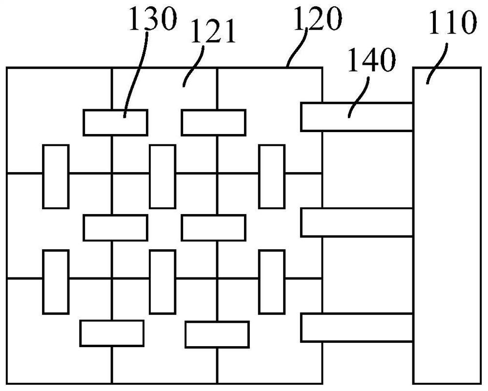
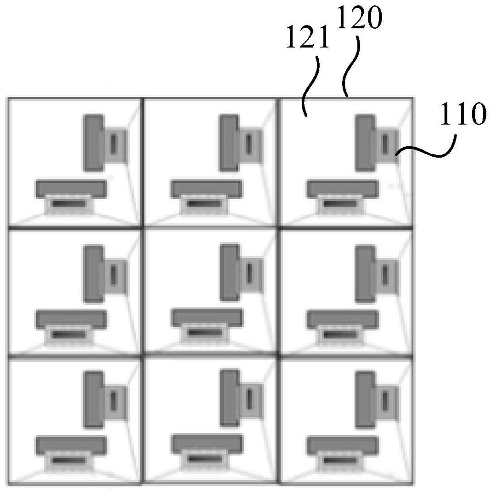
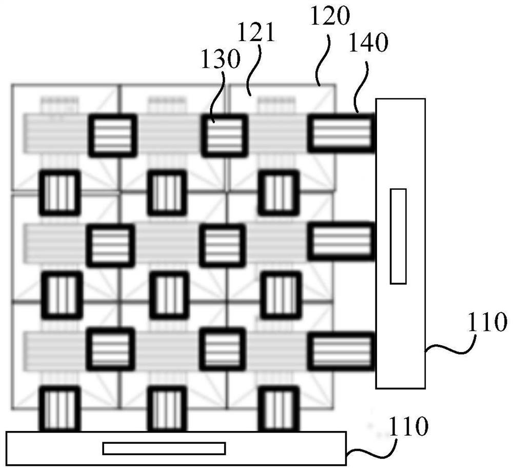
The invention relates to a display panel and a display device. The display panel comprises a driving circuit board and a glass splicing array, the glass splicing array comprises a plurality of glass substrates distributed in an array mode, a first flexible circuit board is bound between each glass substrate and the adjacent glass substrate, and a second flexible circuit board is bound between the glass splicing array and the driving circuit board. The glass substrates in the glass splicing array are electrically connected through the first flexible circuit board, and the glass splicing array is electrically connected with the driving circuit board through the second flexible circuit board, so that driving signals are provided for all the glass substrates in the glass splicing array through one driving circuit board; the driving circuit board does not need to be independently provided for each glass substrate, so that the number of the driving circuit boards is reduced, excessive use of the driving capability of a plurality of driving circuit boards and the number of IC channels is prevented, and the cost of driving hardware can be reduced.

Description

technical field [0001] The present application relates to the technical field of display panels, in particular to a display panel and a display device. Background technique [0002] AM mini LED (Active MatrixminiLight Emitting Diode, Active Matrix mini Light Emitting Diode) and Micro LED (MicroLight Emitting Diode, Micro Light Emitting Diode) display solutions, as important emerging display technologies, have broad development in many application fields of commercial display and home use Prospects, unlike LCD (LiquidCrystal Display, liquid crystal display) and AMOLED (Active-matrix organic light-emitting diode, active-matrix organic light-emitting diode), such large-scale high-resolution single-chip display solutions, are limited by transfer technology And other factors, AM Mini LED and Micro LED mostly use low-resolution small-size glass substrates (Chips) for splicing to achieve large-scale applications, which has the advantages of flexible splicing size and resolution, an...

Claims


Application Information

Patent Timeline
IPC IPC(8): G09G3/32G09G3/3225G09G3/3266H05K1/02
CPCG09G3/32G09G3/3225G09G3/3266H05K1/028
Inventor 王利民
Owner SHENZHEN CHINA STAR OPTOELECTRONICS SEMICON DISPLAY TECH CO LTD
Learn More