
Arch-shaped metal part conveying and adjusting equipment for machine tool assembly

A technology for adjusting equipment and parts, applied in packaging and other directions, can solve problems such as parts prone to negligence or omissions, affecting the normal operation of the baler, and outdated methods

Inactive Publication Date: 2022-04-22
世科工业设计沧州有限公司
View PDF0 Cites 0 Cited by
  • Summary
  • Abstract
  • Description
  • Claims
  • Application Information

AI Technical Summary

Problems solved by technology

[0003] The bow-shaped parts are mainly processed by stamping. In order to facilitate the packaging and transportation of the bow-shaped parts, they need to be arranged neatly. The workers adjust the direction of the bow-shaped parts one by one to the same direction and arrange them neatly, and then pack them with a baler. However, due to the large number of parts, the work of manually adjusting and arranging parts is relatively cumbersome, and the method is relatively old, which consumes more manpower and time, and the work efficiency is low. Negligence, resulting in parts with opposite directions in the neatly arranged parts, which will easily affect the normal work of the subsequent baler

Method used

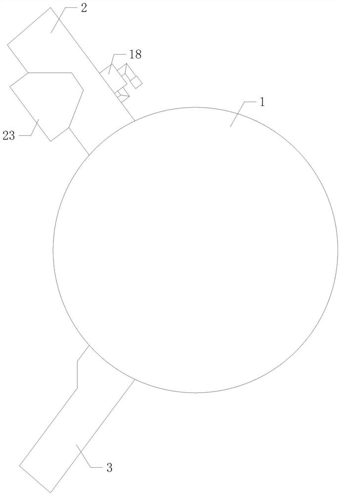
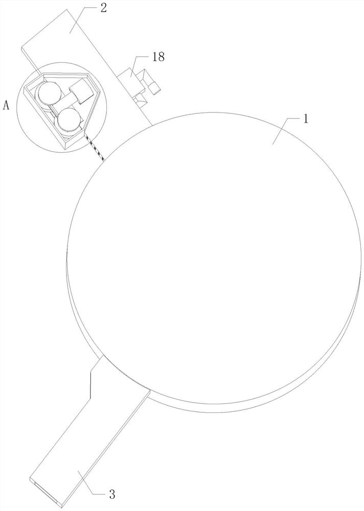
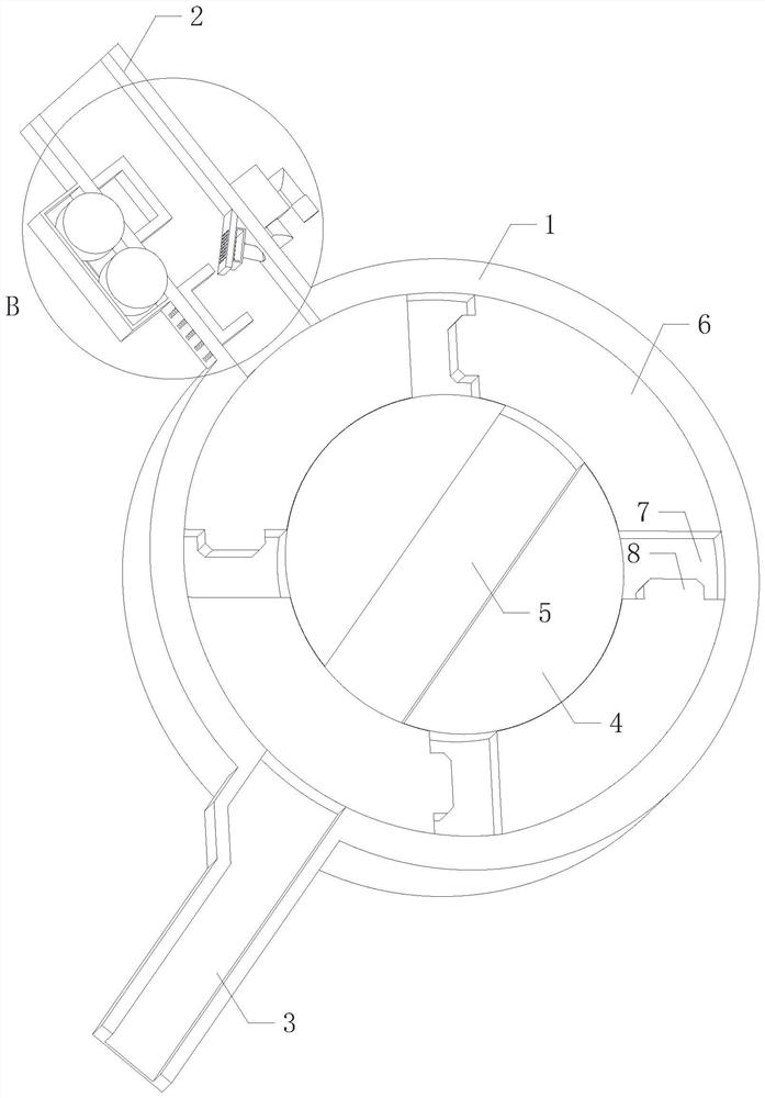

Image

  • Arch-shaped metal part conveying and adjusting equipment for machine tool assembly
  • Arch-shaped metal part conveying and adjusting equipment for machine tool assembly
  • Arch-shaped metal part conveying and adjusting equipment for machine tool assembly

Examples


Embodiment Construction

[0029] The following will clearly and completely describe the technical solutions in the embodiments of the present invention with reference to the accompanying drawings in the embodiments of the present invention. Obviously, the described embodiments are only some, not all, embodiments of the present invention.

[0030] In the description of the present invention, it needs to be explained that, belonging to "center", "upper", "lower", "left", "right", "vertical", "horizontal", "inner", "outer" etc. The indicated orientation or positional relationship is based on the orientation or positional relationship shown in the drawings, and is only for the convenience of describing the present invention and simplifying the description, rather than indicating or implying that the referred device or element must have a specific orientation, or in a specific orientation. construction and operation, therefore, should not be construed as limiting the invention.

[0031] In the description o...


PUM


Abstract

The invention relates to the technical field of mechanical equipment, in particular to arched metal part conveying and adjusting equipment for machine tool assembling, which comprises a circular bin internally provided with a cavity, and a feeding square pipe and a discharging square pipe are obliquely and symmetrically arranged on the upper side and the lower side of the circular bin respectively; the feeding square pipe and the discharging square pipe are both communicated with the interior of the circular bin, a core shaft is longitudinally arranged in the circular bin, the front end face of the core shaft is obliquely communicated with a material guide groove, and the direction of the material guide groove corresponds to the direction of the discharging square pipe. By achieving the purpose of automatically adjusting the directions of the arch-shaped parts, the arch-shaped parts with the directions adjusted can be conveniently and uniformly arranged, the part adjusting mode is simplified, manpower and time are saved, the working efficiency is improved, meanwhile, the phenomenon that the directions of the parts are inconsistent due to negligence or careless mistakes of workers is avoided, and the production efficiency is improved. Follow-up equipment can conveniently package the parts, and the practicability is improved.

Description

technical field [0001] The invention relates to the technical field of mechanical equipment, in particular to a conveying and adjusting device for bow-shaped metal parts used in machine tool assembly. Background technique [0002] As we all know, CNC machine tools are assembled from a lot of metal parts. One of the bow parts is the main part of the rotating shaft of the cutter head in the turret on the machine tool. It fixes the rotating shaft and adjusts the tool The extension and retraction movement of the disc acts as a support. [0003] The bow-shaped parts are mainly processed by stamping. In order to facilitate the packaging and transportation of the bow-shaped parts, they need to be arranged neatly. The workers adjust the direction of the bow-shaped parts one by one to the same direction and arrange them neatly, and then pack them with a baler. However, due to the large number of parts, the work of manually adjusting and arranging parts is relatively cumbersome, and ...

Claims


Application Information

Patent Timeline
Patent Type & Authority Applications(China)
IPC IPC(8): B65B35/58
CPCB65B35/58
Inventor 高洪庆
Owner 世科工业设计沧州有限公司
Learn More