
Channel body, connection device, end wall, drain channel, device and method

A technology for connecting equipment and drains, used in the fields of connecting equipment, drains, polymer concrete, end walls, and installations

Pending Publication Date: 2022-04-22
ACO AHLMANN SE & CO KG
View PDF1 Cites 0 Cited by
  • Summary
  • Abstract
  • Description
  • Claims
  • Application Information

AI Technical Summary

Problems solved by technology

In the known state of the art, especially concrete section joints as well as butt joints and connection joints form critical areas that must be permanently liquid-tight and not allowed as maintenance joints

Method used


Image

  • Channel body, connection device, end wall, drain channel, device and method
  • Channel body, connection device, end wall, drain channel, device and method
  • Channel body, connection device, end wall, drain channel, device and method

Examples


Embodiment Construction

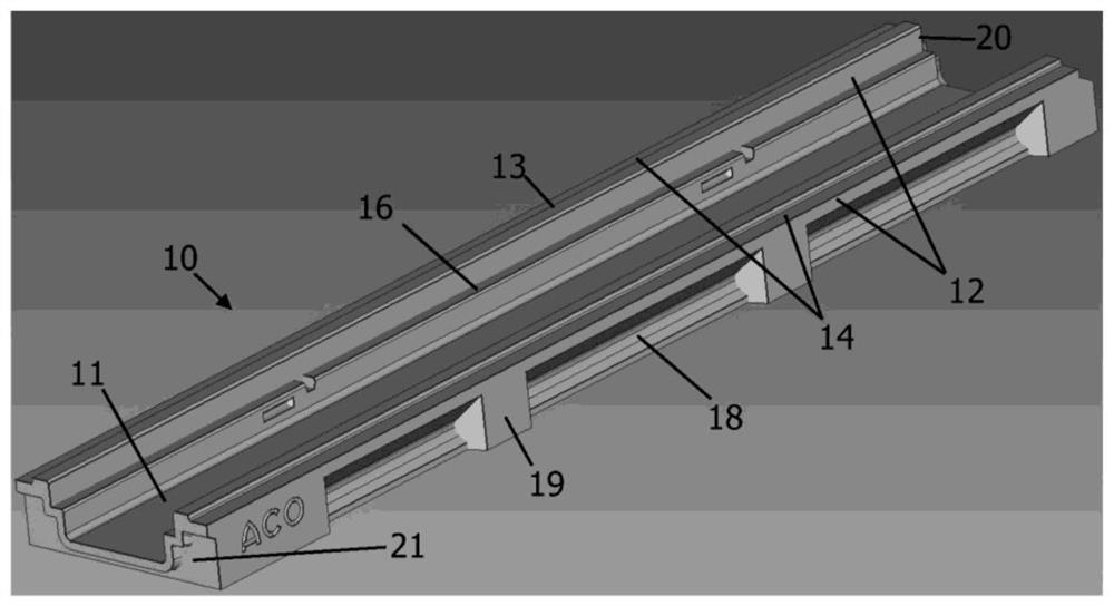
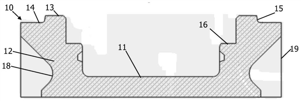
[0070] according to Figure 1 and 2 The channel body 10 is made of polymer concrete and includes a channel bottom 11, two side walls 12 and two free axial ends 20, 21.

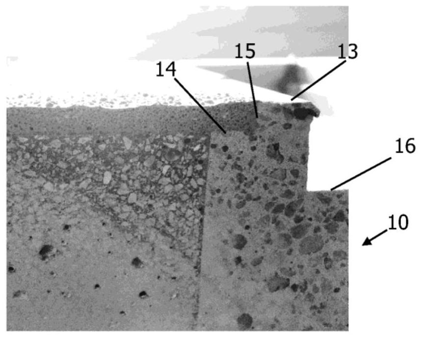
[0071] The side wall 12 has visible contacts 13, respectively. It can be seen that the connector 13 is the uppermost surface of the channel body 10 in the mounted state. The overlay 14 is adjacent to the visible taping 13. Cladding 14 indented from the visible joint 13 via step 15.

[0072] at Figure 2 As can be seen, the overlay layer 14 is disposed in the vertical direction between the visible splicing 13 and the supporting surface 16. The overlay 14 is parallel to the surface of the visible splicing 13. The overlay 14 is continuously disposed on the visible splices 13. The cladding level 14 does not have an interrupt section and is composed smoothly. The overlay 14 forms the outermost pointing surface of the channel body 10 in the mounted state. The cladding level 14 extends along the entire length of the chann...


PUM


Abstract

The invention relates to a channel body of a drainage channel for draining traffic areas, in particular parking platforms, parking garages and / or parking buildings, which channel body is made in particular of polymer concrete or cement concrete, comprising a channel base (11) and two opposite side walls (12), wherein the side walls (12) have visible webs (13) which extend in the longitudinal direction of the channel body (10). The invention is further characterized in that the coating surfaces (14) for surface coating are in each case adjacent to the visible webs (13) and retracted from the visible webs (13) by steps (15), the coating surfaces (14) extending continuously in the longitudinal direction of the channel body (10).

Description

Technical field [0001] The present invention relates to a drainage channel body for draining a traffic area, the channel body is made of polymer concrete in particular. The present invention further relates to a connecting device, end wall, drainage channel, apparatus and method. Background [0002] Drainage channels having the above type of channel body are known, for example, from EP2899324A1. The channel body of a known drainage channel comprises a bottom of the ditch and two opposed sidewalls, the sidewalls having visible joints (Sichtsteg). [0003] In the case of parking platforms, parking garages and / or parking buildings, the plane of guided water can be located on a drivable traffic area. Thus, the traffic area consists of a surface cladding that serves as the uppermost paving surface. Drainage channels that should be installed in such an environment must meet high requirements. Therefore, the space available for installing drainage channels is limited. Therefore, the in...

Claims


Application Information

Patent Timeline
IPC IPC(8): E03F3/04E03F3/06
CPCE03F3/046E03F5/0401E01C11/227E03F5/0409E03F3/06
Inventor 克里斯托弗·佩里奇丹尼尔·哈尔特
Owner ACO AHLMANN SE & CO KG
Features
  • Generate Ideas
  • Intellectual Property
  • Life Sciences
  • Materials
  • Tech Scout
  • Unparalleled Data Quality
  • Higher Quality Content
  • 60% Fewer Hallucinations
Learn More