

Rotating electric machine
A technology for rotating electrical machines and rotors, applied in electromechanical devices, electrical components, electrical components, etc., can solve the problems of temperature sensor deformation, reduced reliability of rotating electrical machines, temperature deviation of stator coils, etc., to suppress deformation, suppress offset, improve The effect of reliability
- Summary
- Abstract
- Description
- Claims
- Application Information
AI Technical Summary
Problems solved by technology
Method used
Image

Examples
Embodiment approach 1
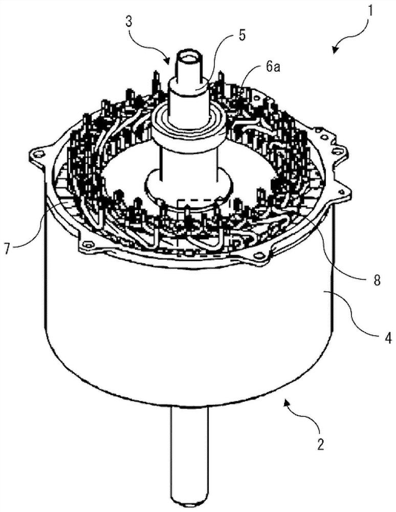
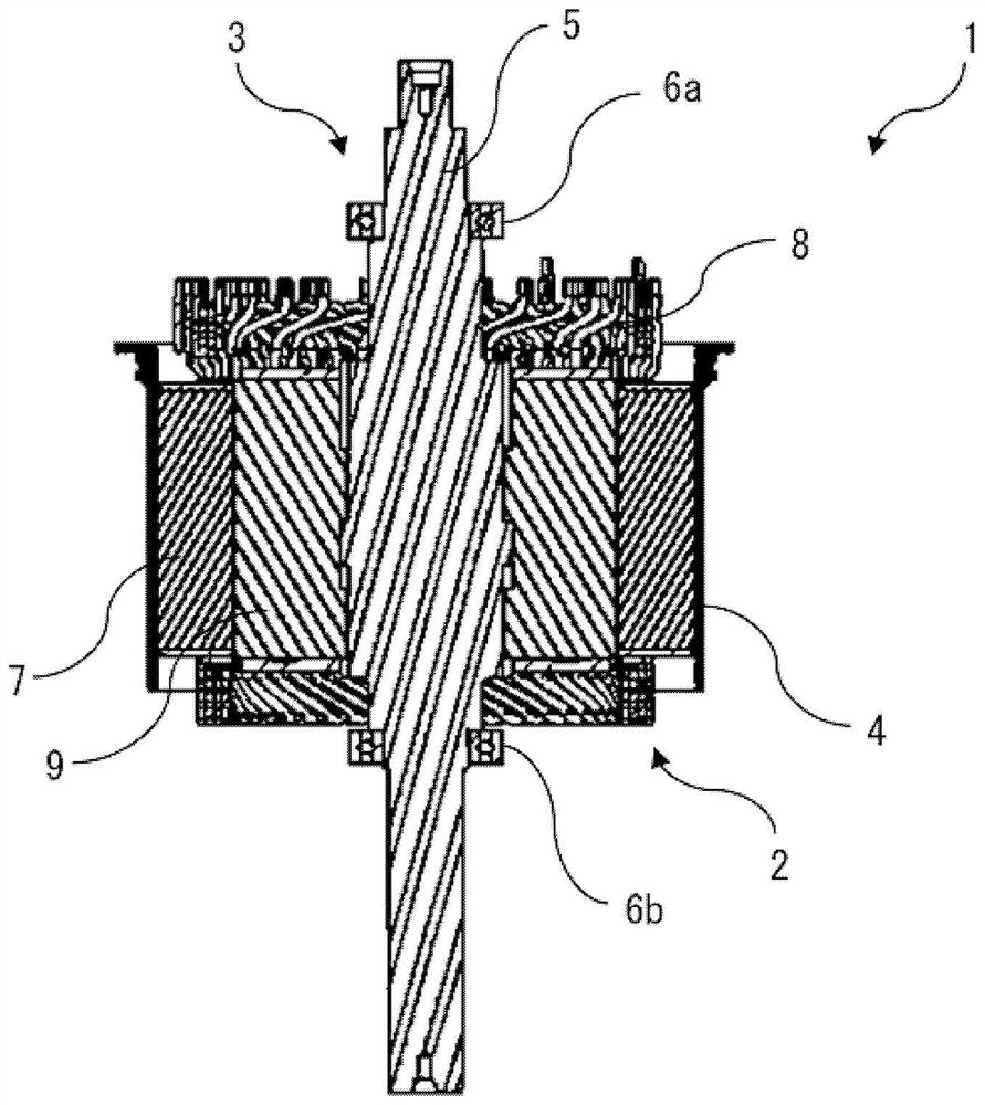
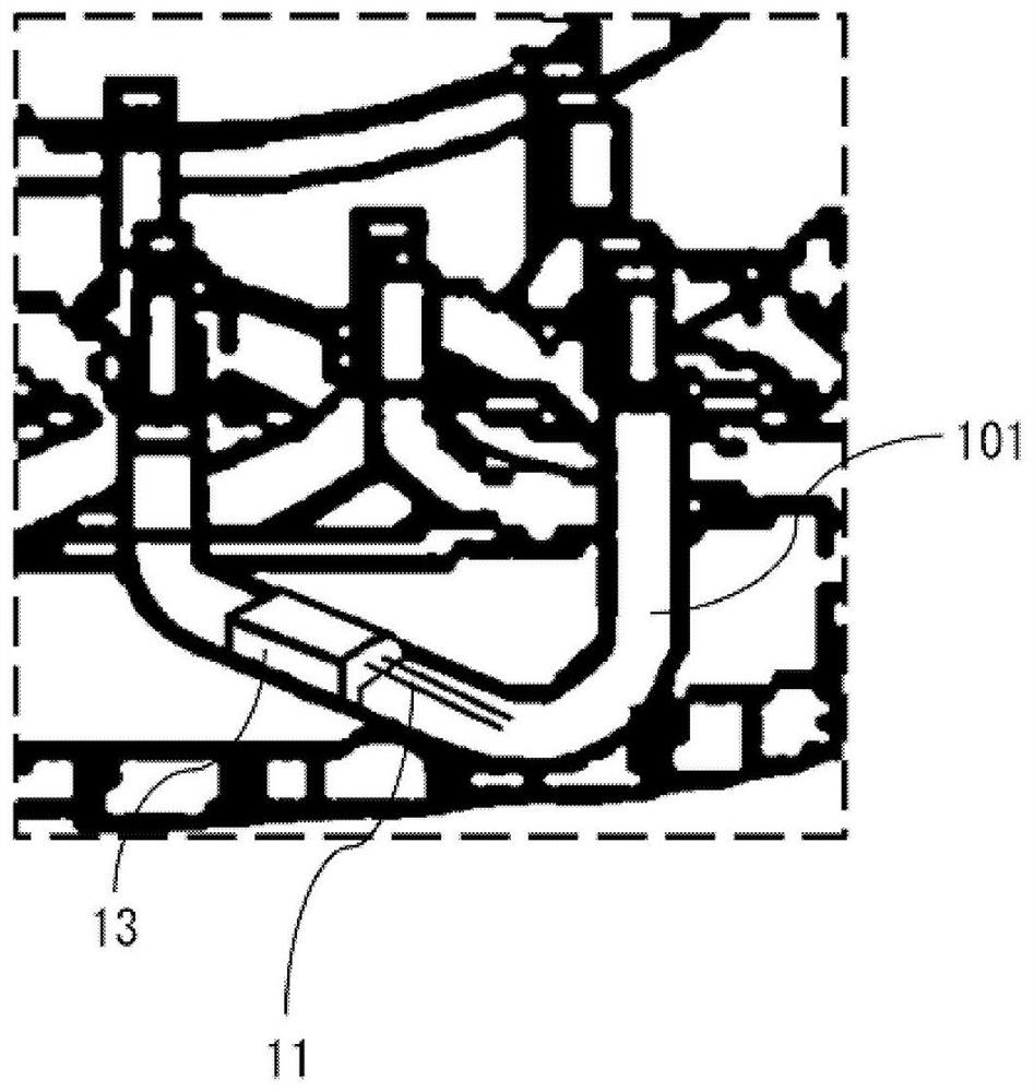
[0066] figure 1 It is a perspective view showing the outline of the rotating electrical machine 1 according to Embodiment 1, figure 2 is a cross-sectional view showing the outline of the rotating electrical machine 1 and parallel to the axial direction of the rotating electrical machine 1, image 3 It is to install the temperature sensor 11 and the mounting member 13 of the rotating electrical machine 1, by figure 1 The perspective view of the main part shown enlarged by the part enclosed by the dotted line, Figure 4 is a perspective view of the additional wire 101, the temperature sensor 11, and the mounting member 13 of the rotating electrical machine 1, Figure 5 is a front view of the additional wire 101 of the rotating electrical machine 1, the temperature sensor 11 and the mounting member 13, Figure 6 is a plan view of the additional wire 101, the temperature sensor 11 and the mounting member 13 of the rotating electrical machine 1, Figure 7 is in Figure 6 A cr...
Embodiment approach 2
[0081] The rotating electrical machine 1 according to Embodiment 2 will be described. Figure 8 is the additional wire 101, the temperature sensor 11, and the mounting member 13 of the rotating electric machine 1 according to the second embodiment. Figure 6 A cross-sectional view cut at the same position as the A-A cross-section, Figure 9 is in Figure 8 The cross-sectional view of the additional line 101 and the mounting member 13 cut off at the position of the B-B cross-section, Figure 10 is in Figure 8 A sectional view of the additional line 101 and another mounting member 13 cut at the B-B section position of . The rotating electrical machine 1 according to the second embodiment is configured such that the mounting member 13 also covers the surface 102 c of the main body 102 opposite to the surface provided with the concave portion 104 .
[0082] Such as Figure 8 As shown, the attachment member 13 is attached to the main body 102 so as to cover the entire portion...
Embodiment approach 3
[0086] The rotating electrical machine 1 according to Embodiment 3 will be described. Figure 11 is the additional wire 101, the temperature sensor 11, and the mounting member 13 of the rotating electric machine 1 according to the third embodiment. Figure 6 A cross-sectional view cut at the same position as the A-A cross-section. The rotating electrical machine 1 according to Embodiment 3 has a configuration in which the arrangement of the sensor unit 12 of the temperature sensor 11 is different.
[0087] The sensor unit 12 of the temperature sensor 11 is arranged at a position facing the bottom 104 a of the recess 104 . In Embodiment 1, such as Figure 7 As shown, the sensor part 12 of the temperature sensor 11 is arranged at the end of the recessed part 104 . If the arrangement of the sensor part 12 deviates from the end part of the recessed part 104 toward the bottom 104 a side, the distance between the sensor part 12 and the main body part 102 becomes longer. When the...
PUM
 Abstract
Description
Claims
Application Information