
Solar panel mounting device

A technology for installing devices and solar panels, which is applied to photovoltaic power generation, photovoltaic modules, electrical components, etc., can solve the problems of non-adjustable angle and low absorption efficiency of solar panels, and achieve the effect of improving efficiency and convenient use.

Pending Publication Date: 2022-04-22
欧阳宝清
View PDF0 Cites 0 Cited by
  • Summary
  • Abstract
  • Description
  • Claims
  • Application Information

AI Technical Summary

Problems solved by technology

[0003] However, most of the existing solar mounting frames are designed as fixed structures. When the solar panel is installed on the mounting frame, its angle cannot be adjusted, so that the solar panel can only absorb sunlight in the same direction, resulting in solar energy The efficiency of solar panels absorbing sunlight is low, therefore, in view of the above situation, it is necessary to design a solar panel installation device that can automatically adjust the angle of solar panels

Method used


Image

  • Solar panel mounting device
  • Solar panel mounting device
  • Solar panel mounting device

Examples


Embodiment 1

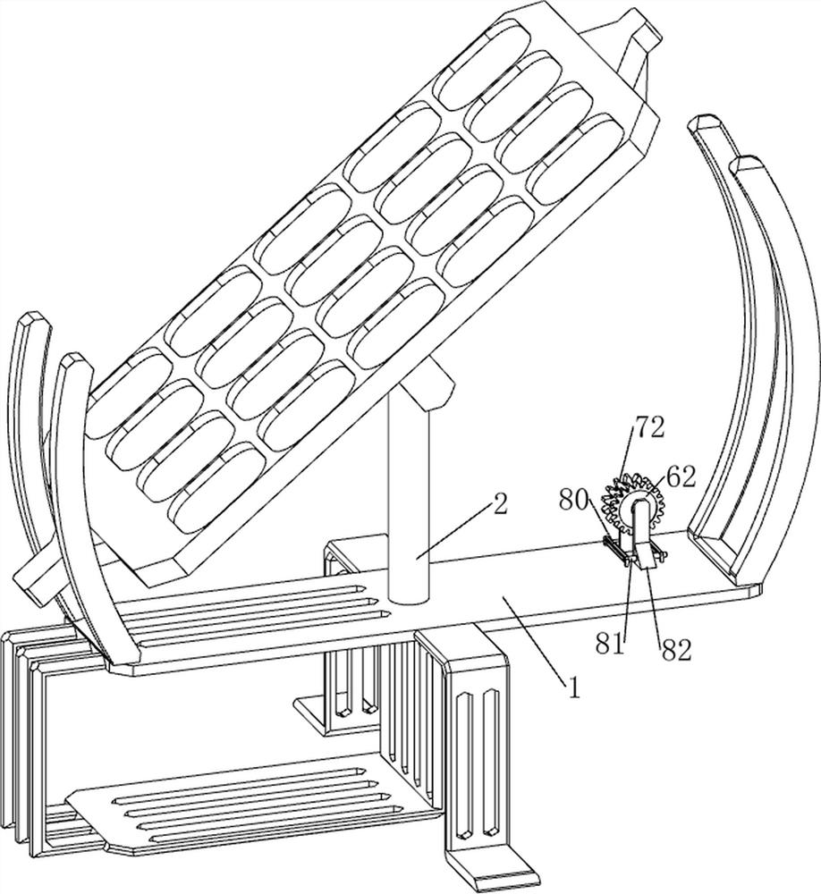
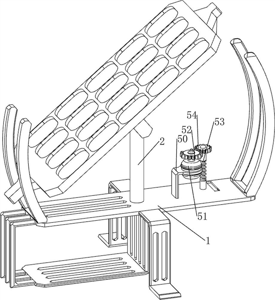
[0065] A solar panel mounting device, such as Figure 1 、 Figure 2 、 Figure 3 、 Figure 4 and Figure 5 Shown, including the first support plate 1, the first fixed column 2, the first shaft 3, the first fixed plate 4, the transmission mechanism 5, the deceleration mechanism 6 and the pulling mechanism 7, the first support plate 1 is provided with the first fixed column 2 on the top middle side, the first fixed column 2 is provided with the first rotating type 3, the first shaft 3 is provided with a first fixed plate between the front and rear sides 4, the first support plate 1 is provided with a transmission mechanism 5 on the right side of the top, the first support plate 1 is provided with a deceleration mechanism 6 on the top right side, and the deceleration mechanism 6 is located on the right side of the transmission mechanism 5. The first support plate 1 is provided with a pull mechanism 7 on the right side of the top, and the pull mechanism 7 is located on the right side of th...

Embodiment 2

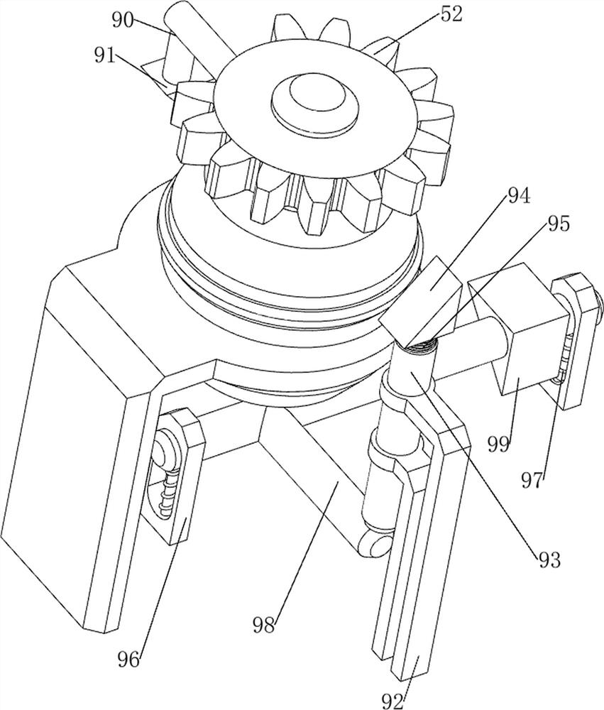
[0071] On the basis of Example 1, e.g., Figure 1 、 Figure 6 、 Figure 7 、 Figure 8 、 Figure 9 、 Figure 10 and Figure 11Shown, further comprising a manual release mechanism 8, manual release mechanism 8 comprising a third fixed plate 80, a first movable column 81, a first wedge block 82 and a first spring 83, the first support plate 1 on the top right side of the two third fixed plates 80, the third fixed plate 80 are located between the worm 53 and the third support plate 70, the second support plate 60 is located between the third fixed plate 80, the third fixed plate 80 between the upper front side of the sliding type is provided with a first movable column 81, the first moving column 81 is provided with a first wedge block 82 on the middle side The first wedge-shaped block 82 is connected to the front side of the second support plate 60, and the first moving column 81 is equipped between the left and right sides of the rear side and the third fixed plate 80.

[0072] When peo...


PUM


Abstract

The invention relates to a mounting device, in particular to a solar panel mounting device. The technical problem to be solved is to provide a solar panel mounting device capable of automatically adjusting the angle of a solar panel. The solar panel mounting device comprises a first supporting plate and a first fixing column, and the first fixing column is arranged on the middle side of the top of the first supporting plate; the first rotating shaft is rotationally arranged at the upper part of the first fixed column; the first fixing plate is arranged between the two sides of the first rotating shaft; the transmission mechanism is arranged on one side of the top of the first supporting plate; the speed reducing mechanism is arranged on one side of the top of the first supporting plate, and the speed reducing mechanism is located on one side of the transmission mechanism; and the pulling mechanism is arranged on one side of the top of the first supporting plate. Through cooperation of the transmission mechanism, the speed reducing mechanism and the pulling mechanism, the angle of the solar cell panel can be automatically adjusted, and the sunlight absorption efficiency of the solar cell panel is improved.

Description

Technical field [0001] The present invention relates to an installation device, in particular to a solar panel mounting device. Background [0002] At present, solar energy has become an important part of human use of clean energy, and continue to be developed, solar energy in modern generally used as power generation or for water heaters to provide energy, the use of solar energy has two ways of photothermal conversion and photoelectric conversion, no matter which conversion method, it is necessary to use panels to convert light energy, therefore, solar panel installation device is an indispensable device in the use of solar energy. [0003] However, the existing solar mounting frame, mostly for the fixed structure of the design, when the solar panel is installed on the mounting frame after its angle is not adjustable, so that the solar panel can only be a single in the same direction to absorb sunlight, resulting in the solar panel absorption of sunlight is less efficient, the...

Claims


Application Information

Patent Timeline
Patent Type & Authority Applications(China)
IPC IPC(8): H02S20/30H02S20/32
CPCH02S20/30H02S20/32Y02E10/50
Inventor 欧阳宝清
Owner 欧阳宝清
Learn More